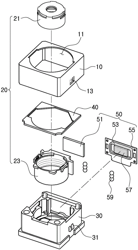
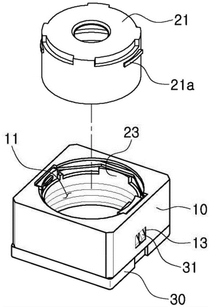
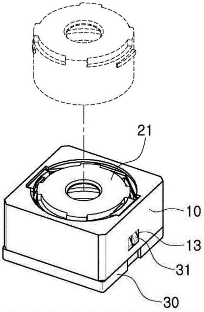
A camera module

A camera module and lens module technology, applied in the field of camera modules, can solve the problems of camera module scrap, separate lens maintenance, etc., and achieve the effect of miniaturization

Inactive Publication Date: 2017-01-04
SAMSUNG ELECTRO MECHANICS CO LTD
View PDF6 Cites 20 Cited by
  • Summary
  • Abstract
  • Description
  • Claims
  • Application Information

AI Technical Summary

Problems solved by technology

[0006] Furthermore, when the lens provided in the lens barrel becomes defective, the camera module itself has

Method used


Image

  • A camera module
  • A camera module
  • A camera module

Examples


Example Embodiment

[0031] Hereinafter, embodiments of the present disclosure will be described with reference to the drawings.

[0032] However, the present disclosure can be implemented in many different forms, and should not be construed as being limited to the embodiments set forth herein. Rather, these embodiments are provided so that the present disclosure will be thorough and complete, and fully convey the scope of the present disclosure to those skilled in the art.

[0033] Throughout the specification, it will be understood that when an element such as a layer, region, or substrate is referred to as being “on”, “connected to,” or “coupled to” another element, the element may It is directly “on” another element, directly “connected to” or directly “coupled to” another element, or there may be other elements in between. In contrast, when an element is referred to as being "directly on", "directly connected to", or "directly coupled to" another element, there are no intervening elements or laye...


PUM


Abstract

The invention provides a camera module which is configured to allow magnetic attraction force to be generated between a magnet and an outer shell forming the appearance of the camera module so as to meet the requirement of miniaturization. Moreover, the camera module comprises a frame combined to the shell and a lens barrel combined the frame according to changeable states. The lens barrel which can employ lenses of different specifications can be applied in the camera module.

Description

[0001] This application claims the priority and benefits of Korean Patent Applications No. 10-2015-0089336 and No. 10-2015-0173839 filed with the Korean Intellectual Property Office on June 23, 2015 and December 8, 2015, respectively, so The disclosure of said application is hereby incorporated by reference. technical field [0002] The present disclosure relates to a camera module. Background technique [0003] Camera modules have been manufactured with an image sensor such as a Charge Coupled Device (CCD) or a Complementary Metal Oxide Semiconductor (CMOS) as a main component. Such a camera module obtains an image of a subject through an image sensor to store the data in a memory of the device, and displays the stored data as an image through a display medium (eg, LCD) included in the device. [0004] Also, a camera module including an image sensor generally has a function of performing auto focus or zoom. [0005] When a magnet provided as an actuator for autofocus is d...

Claims


Application Information

Patent Timeline
IPC IPC(8): G02B7/09G03B13/36H04N5/225
CPCG02B7/09G03B13/36H04N23/55
Inventor 李重锡金暻准金裕倡金圣熏金满洙白在皓金浦哲李明基
Owner SAMSUNG ELECTRO MECHANICS CO LTD
Why Eureka
Try Eureka