A display device and image display method

A technology of display device and display module, which is applied in image communication, light guide, optics, etc., and can solve problems such as dizziness of human eyes, failure to provide single-eye focus light direction information, discomfort, etc.

Active Publication Date: 2017-01-04
BOE TECH GRP CO LTD
View PDF5 Cites 22 Cited by
  • Summary
  • Abstract
  • Description
  • Claims
  • Application Information

AI Technical Summary

Problems solved by technology

However, in the current parallax 3D world, such as Figure 1b As shown, since the screen only provides the binocular parallax image of the observed light field, but does not provide the corresponding light direction information required for monocular focusing, so that the focus position of the monocular is always on the screen, w...

Method used


Image

  • A display device and image display method
  • A display device and image display method
  • A display device and image display method

Examples


Embodiment 1

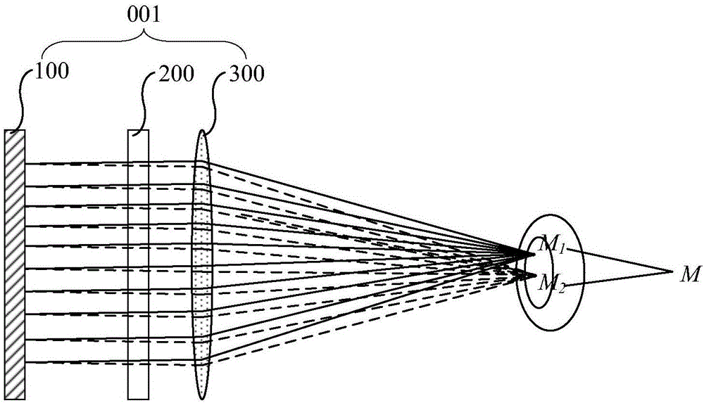
[0074] Such as Figure 6 As shown, the backlight module 100 includes a grating waveguide coupling structure 110, and the grating waveguide coupling structure 110 includes a waveguide layer 111, a grating structure 112 disposed on the upper surface of the waveguide layer 111, and an upper dielectric layer 113 above the waveguide layer 111 and a Lower dielectric layer 114, and the refractive index of upper dielectric layer 113 and lower dielectric layer 114 are all smaller than the refractive index of waveguide layer 111, for example, can choose the refractive index of waveguide layer 111 1.7~1.8, upper dielectric layer 113 and lower dielectric layer The refractive index of 114 is 1.5 to achieve better optical coupling effect. The backlight module 100 also includes at least one collimated backlight 120 disposed on the side of the waveguide layer 111 , and each collimated backlight 120 as a whole is used to emit collimated light in at least two different directions.

[0075] It ...

Embodiment 2

[0101] Such as Figure 3c As shown, the backlight module 100 can also be a direct-type backlight module, which can emit collimated light rays in at least two different directions ( Figure 3c Only two collimated light rays in different directions are taken as an example for illustration), so that the purpose of the backlight module 100 emitting at least two collimated light rays in different directions can be achieved.

[0102] An embodiment of the present invention also provides an image display method applied to any of the above display devices 001, such as Figure 13 As shown, the image display method includes:

[0103] Step S101 , controlling the backlight module to periodically and sequentially emit S collimated light rays in different directions.

[0104] Step S102, when the backlight module emits collimated light in any direction, input to the display module a frame of rendered image corresponding to the preset viewpoint where the collimated light in this direction co...


PUM

PropertyMeasurementUnit
Thicknessaaaaaaaaaa
Thicknessaaaaaaaaaa
Thicknessaaaaaaaaaa

Abstract

The invention provides a display device and image display method which is related to display technology filed. The display device is able to provide hardware support for the same monocular focus distance and binocular convergence distance. The display device comprises sequentially set backlight module, display module and light directing component. The backlight module is used for periodically sending out S collimated lights in different directions. The collimated lights in different directions go through the display module to reach the light directing component, wherein S>=2. The light directing component is used for collecting the collimated lights with the same incident direction to the same preset viewpoint, and different incident directions to the different preset viewpoints. Wherein, the preset viewpoints belonging to the same eye among S preset viewpoints constitute a viewpoint group, and the viewpoint group contains at least two preset viewpoints, while different viewpoint groups locate in different eyeballs.

Description

technical field [0001] The present invention relates to the field of display technology, in particular to a display device and an image display method. Background technique [0002] With the advancement of technology, image display is no longer limited to two-dimensional space (2D) screen planes, and three-dimensional space (3D) picture display is more and more used in people's daily work, study and entertainment. [0003] In the real world, such as Figure 1a As shown, when the normal human eyes watch the object O, the line-of-sight convergence distance L of both eyes is equal to the focusing distance L' of the single eye, that is, the focus position is on the observed object O. However, in the current parallax 3D world, such as Figure 1b As shown, since the screen only provides the binocular parallax image of the observed light field, but does not provide the corresponding light direction information required for monocular focusing, so that the focus position of the mono...

Claims


Application Information

Patent Timeline
IPC IPC(8): G02B27/22G02B30/33
CPCG02B30/34G02B30/27H04N13/32G02B27/4205G02B6/0076G02B6/005G02B30/33H04N13/305G02B6/0068
Inventor 王维杨亚锋陈小川
Owner BOE TECH GRP CO LTD
Why Eureka
Try Eureka