A rocker switch

A rocker and switch technology, applied in the direction of flip switch/rocker switch components, etc., can solve the problem of affecting the closing and opening of the switch, easy to abut on the side of the rocker, and the rocker is not tilted in place, etc. question

Active Publication Date: 2019-03-01
ZHEJIANG ERA ELECTRICAPPLIANCE CO LTD
View PDF6 Cites 0 Cited by
  • Summary
  • Abstract
  • Description
  • Claims
  • Application Information

AI Technical Summary

Problems solved by technology

In this way, after a long time of use, the spring will be deformed, that is, the spring will bend, so that the degree of freedom of the spring and the spring sleeve in the spring hole will increase, causing the spring sleeve to shake in the spring hole in the circumferential direction
On the other hand, the rocker will also shift after a long time of use, making the relative positional relationship between the spring sleeve and the rocker more likely to shift. Therefore, when the spring bends toward the two sides of the rocker, press the After the button is pressed, the spring is easy to lean against the side of the rocker, and even the spring cover will slide out of the stroke of the rocker, which will cause the rocker to not move in place, affect the closing and opening of the switch, and cause the switch to fail

Method used


Image

  • A rocker switch
  • A rocker switch
  • A rocker switch

Examples


Embodiment Construction

[0023] The following are specific embodiments of the present invention and in conjunction with the accompanying drawings, the technical solutions of the present invention are further described, but the present invention is not limited to these embodiments.

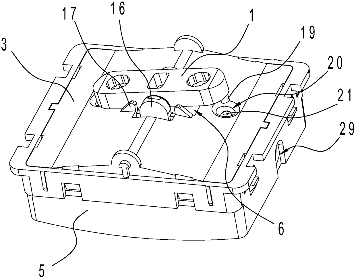
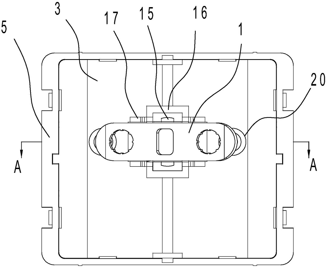
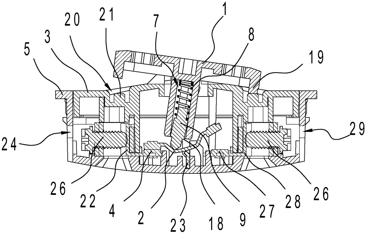
[0024] Such as Figure 1-Figure 3As shown, the seesaw switch includes a key 1, a seesaw 2, an upper cover 3, a first static contact 4 and a base 5, the upper cover 3 is provided with a through hole 6, and the through hole 6 is connected to the long side of the key 1. The hole walls on the corresponding two sides are respectively provided with retaining edges 16, the key 1 is installed in the through hole 6, and the long side of the key 1 is hinged on the retaining edge 16 through the rotating shaft 15, and the two sides of the retaining edge 16 are provided with The baffle 17 , the baffle 17 abuts against the long side of the button 1 . Protrusions 19 are respectively provided under the two ends of the upper part of the b...


PUM


Abstract

The invention provides a rocker plate type switch, belongs to the field of electric appliance switch, and solves the problem that the relative positions of a spring sleeve and a rocker plate in the conventional rocker plate type switch are easily changed. A through hole is formed in the upper cover plate of the rocker plate type switch; a key is mounted in the through hole; the upper cover plate is buckled on the base; the lower part of the key is column-shaped; a spring hole is formed in the center of the key; a spring and a sliding block are mounted inside the spring hole; the upper end of the spring is propped against the bottom of the spring hole; the lower end of the spring is fixedly connected with the upper end of the sliding block; the lower end of the sliding block is propped against the surface of the rocker plate; a first static contact is arranged below one end of the rocker plate; the sliding block is column-shaped; the spring hole is provided with a first side wall, a second side wall, a third side wall and a fourth side wall; the distance between the first side wall and the second side wall is greater than or equal to the diameter of the sliding block; the distance between the first side wall and the second side wall is smaller than the smallest distance between the third side wall and the fourth side wall. The rocker plate type switch is high in closure and opening sensitivity and is stable and durable.

Description

technical field [0001] The invention belongs to the field of electrical switches and relates to a seesaw switch. Background technique [0002] The electrical switch used on the wall is a kind of home decoration functional article, and is a household appliance used to connect and disconnect circuits. In a broad sense, electrical products cover a wide range, generally pointing to equipment that provides power and electrical control to end users, including switch sockets, circuit breakers, integrated wiring, security systems, etc., also known as building electrical accessories for fixing, connecting or opening. The general term for devices used in closed circuits. [0003] In the current existing switch technology, it usually includes a button, a spring, a spring sleeve and a seesaw. On the rocker, the spring sleeve contact rocker moves by pressing the button. For example, the Chinese patent [Application No. 201020599933.4] discloses the following scheme: the structure for p...

Claims


Application Information

Patent Timeline
Patent Type & Authority Patents(China)
IPC IPC(8): H01H23/04H01H23/16
CPCH01H23/04H01H23/16
Inventor 卢震宇於宏战徐伟兵
Owner ZHEJIANG ERA ELECTRICAPPLIANCE CO LTD
Why Eureka
Try Eureka