
A kind of polysilicon etching method

A polysilicon and polysilicon layer technology, which is applied in the manufacture of electrical components, circuits, semiconductors/solid-state devices, etc., can solve problems such as polysilicon residues and lower product yields, so as to improve product yields, reduce polysilicon residual defects, and reduce polysilicon residues The effect of defects

Active Publication Date: 2020-06-09
SEMICON MFG INT (SHANGHAI) CORP
View PDF3 Cites 0 Cited by
  • Summary
  • Abstract
  • Description
  • Claims
  • Application Information

AI Technical Summary

Problems solved by technology

[0007] In view of the above-mentioned shortcomings of the prior art, the purpose of the present invention is to provide a polysilicon etching method for solving the problem of SiN residual particles formed during the etching process of the SiN hard mask in the prior art, resulting in a polysilicon etching process Unnecessary polysilicon residues are generated in the middle, which reduces the problem of product yield

Method used


Image

  • A kind of polysilicon etching method
  • A kind of polysilicon etching method
  • A kind of polysilicon etching method

Examples


Embodiment Construction

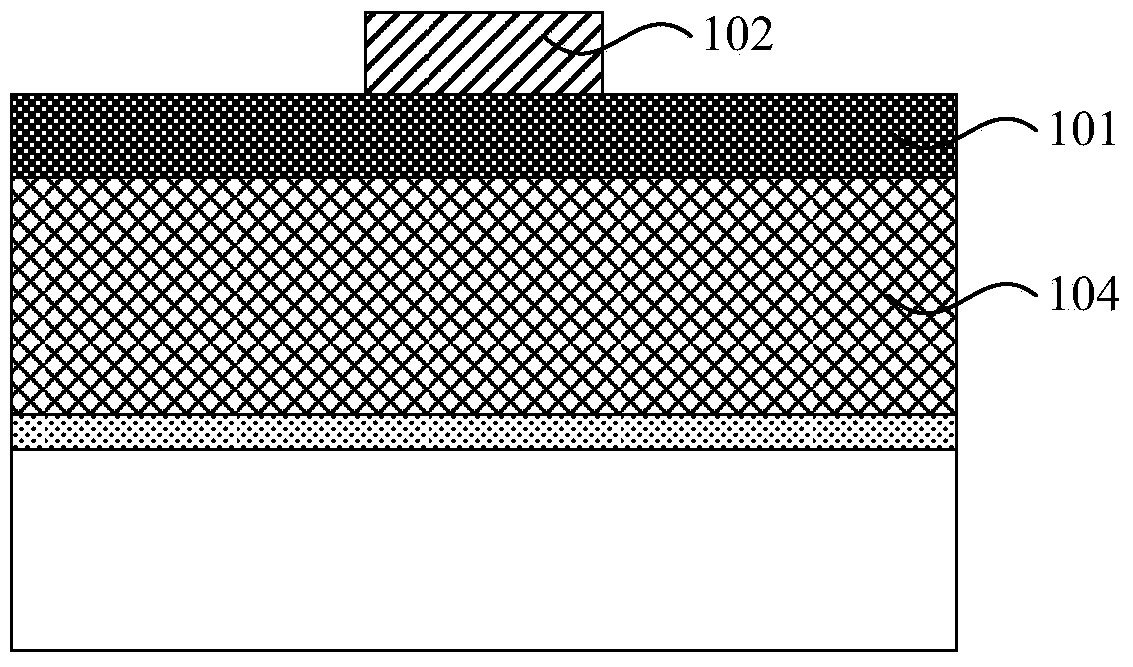
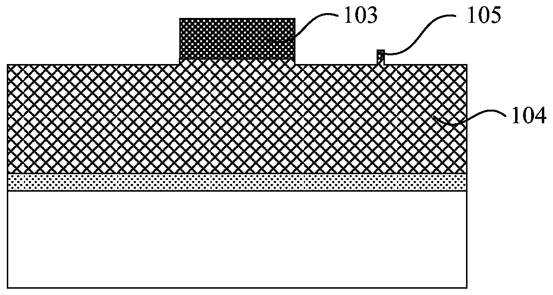
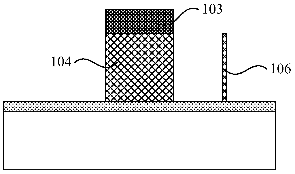
[0046] Embodiments of the present invention are described below through specific examples, and those skilled in the art can easily understand other advantages and effects of the present invention from the content disclosed in this specification. The present invention can also be implemented or applied through other different specific implementation modes, and various modifications or changes can be made to the details in this specification based on different viewpoints and applications without departing from the spirit of the present invention.

[0047] see Figure 4 to Figure 11 . It should be noted that the diagrams provided in this embodiment are only schematically illustrating the basic idea of ​​the present invention, and only the components related to the present invention are shown in the diagrams rather than the number, shape and shape of the components in actual implementation. Dimensional drawing, the type, quantity and proportion of each component can be changed ar...


PUM

PropertyMeasurementUnit
thicknessaaaaaaaaaa
quality scoreaaaaaaaaaa

Abstract

The invention provides a polysilicon etching method. The method comprises the following steps of S1, forming a SiN layer on the surface of a polysilicon layer, etching the SiN layer and patterning the SiN layer to obtain a SiN hard mask layer; S2, forming an oxide layer between SiN residual particles which are not etched thoroughly and on the periphery of the SiN hard mask layer and the polysilicon layer; S3, adopting wet etching to remove the oxide layer, and enabling the SiN residual particles to separate from the polysilicon layer due to suspension; and S4, etching the polysilicon layer taking the SiN hard mask layer as a mask layer. The invention prevents that fact that silicon nitride residual particles obstruct follow-up polysilicon etching, and greatly reduces polysilicon residual defects. With the polysilicon etching method, the photoetching time is not required to be increased, almost no influence on subsequent processes exists, disadvantages of using the traditional DARC as a hard mask layer are successfully avoided, polysilicon residual defects as the SiN serves as the hard mask layer are successfully reduced, and the product yield rate is effectively raised.

Description

technical field [0001] The invention belongs to the field of semiconductor manufacturing and relates to a polysilicon etching method. Background technique [0002] In conventional semiconductor manufacturing processes, polysilicon (polysilicon) is often used as a gate of a MOS device. The formation of the gate often requires the use of silicon nitride (SiN) as a hard mask (Hardmask, HM). Silicon nitride as a hard mask solves the problem that traditional DARC (SiON) as a hard mask is difficult to remove (phosphoric acid is ineffective) after a subsequent high-temperature process. [0003] At present, a MOS device structure formed by double-layer polysilicon can effectively reduce the area of ​​the device, and this unique process has attracted more and more attention. Silicon nitride is also used as a hard mask material in this double-layer polysilicon device. However, in the silicon nitride hard mask process, it is easy to produce a large number of tiny polysilicon residue...

Claims


Application Information

Patent Timeline
Patent Type & Authority Patents(China)
IPC IPC(8): H01L21/306
CPCH01L21/30604
Inventor 赵连国彭坤呼翔王海莲陈文甫罗登贵王峰朱建校徐培明
Owner SEMICON MFG INT (SHANGHAI) CORP
Learn More