Antenna radiator structure and patch antenna thereof

An antenna radiator and patch antenna technology, applied in the field of communication, can solve the problems of poor clutter suppression effect, etc., and achieve the effect of clutter suppression

Active Publication Date: 2017-01-04
COMBA TELECOM SYST CHINA LTD
View PDF2 Cites 9 Cited by
  • Summary
  • Abstract
  • Description
  • Claims
  • Application Information

AI Technical Summary

Problems solved by technology

[0004] Based on this, it is necessary to provide an antenna radiator structure a

Method used


Image

  • Antenna radiator structure and patch antenna thereof
  • Antenna radiator structure and patch antenna thereof
  • Antenna radiator structure and patch antenna thereof

Examples


Embodiment Construction

[0021] Embodiments of the antenna radiator structure and the patch antenna of the present invention will be described below with reference to the accompanying drawings.

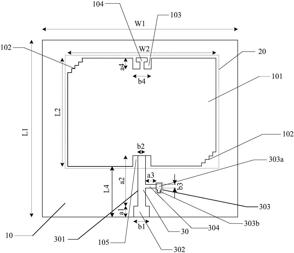
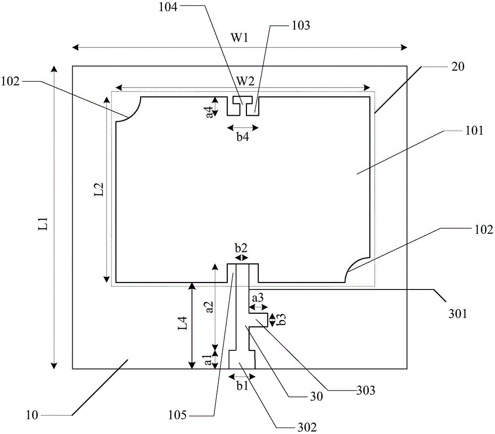
[0022] Antenna radiator structure and patch antenna such as Figure 1 to Figure 3 As shown, the antenna radiator structure of the present invention may include:

[0023] A pair of radiators 101 in a diagonal structure are provided, and the radiators 101 are connected to the feeding part;

[0024] Each of the pair of diagonal structures is provided with a first notch 102 for suppressing clutter, and one side of the radiator 101 is provided with a second notch 103 for suppressing clutter, and all corresponding to the second notch 103 The other side of the radiator 101 is connected to the feeding part.

[0025] Among them, the antenna radiator structure is figure 1 and figure 2 Part of L2×W2 in. The radiator 101 may be a patch, for example, a rectangular or square patch having a pair of diagonal structures...


PUM


Abstract

The invention relates to an antenna radiator structure and a patch antenna thereof. The structure comprises a radiator with a pair of diagonal structures, and the radiator is connected with a feed part. The diagonal structures are respectively provided with a first gap for clutter inhibition, and one side of the radiator is provided with a second gap for clutter inhibition. The other side, opposite to the second gap, of the radiator is connected with the feed part. According to the invention, the antenna is enabled to inhibit clutters in a high-order mode through the first gaps at the opposite corners of a patch and the second gap at the side. The second gap at the side of the patch enables a current path to be prolonged, and the size of the patch is reduced.

Description

technical field [0001] The invention relates to the technical field of communication, in particular to an antenna radiator structure and a patch antenna thereof. Background technique [0002] Antenna is a component that radiates and receives electromagnetic wave energy in systems such as wireless communication, radio and television, satellite communication, navigation, and cordless telephone. role. With the rapid development of modern wireless communications, especially the wide application of WLAN (Wireless LocalArea Network), LTE (Long Term Evolution, long-term evolution) and CDMA (Code Division Multiple Access, Code Division Multiple Access), people are concerned about the performance of the antenna Increasingly demanding. [0003] Due to the complexity of the wireless propagation environment, the antenna often receives clutter from various scatterers when receiving signals. In order to maintain the demodulation quality of the received signal, the antenna needs to have...

Claims


Application Information

Patent Timeline
IPC IPC(8): H01Q1/38H01Q1/50
CPCH01Q1/38H01Q1/50
Inventor 赵琦邱桥春
Owner COMBA TELECOM SYST CHINA LTD
Why Eureka
Try Eureka