Moving target detector utilizing time delay FRFT mode difference

A technology of moving targets and detectors, applied in the direction of utilizing re-radiation, instruments, measuring devices, etc., can solve problems such as limited applications, achieve good real-time performance, simple algorithm, and improve the effect of signal-to-clutter ratio

Inactive Publication Date: 2010-11-10
NAVAL AERONAUTICAL & ASTRONAUTICAL UNIV PLA
View PDF0 Cites 10 Cited by
  • Summary
  • Abstract
  • Description
  • Claims
  • Application Information

AI Technical Summary

Problems solved by technology

The above problems limit the practical application of these methods

Method used


Image

  • Moving target detector utilizing time delay FRFT mode difference
  • Moving target detector utilizing time delay FRFT mode difference

Examples


Embodiment Construction

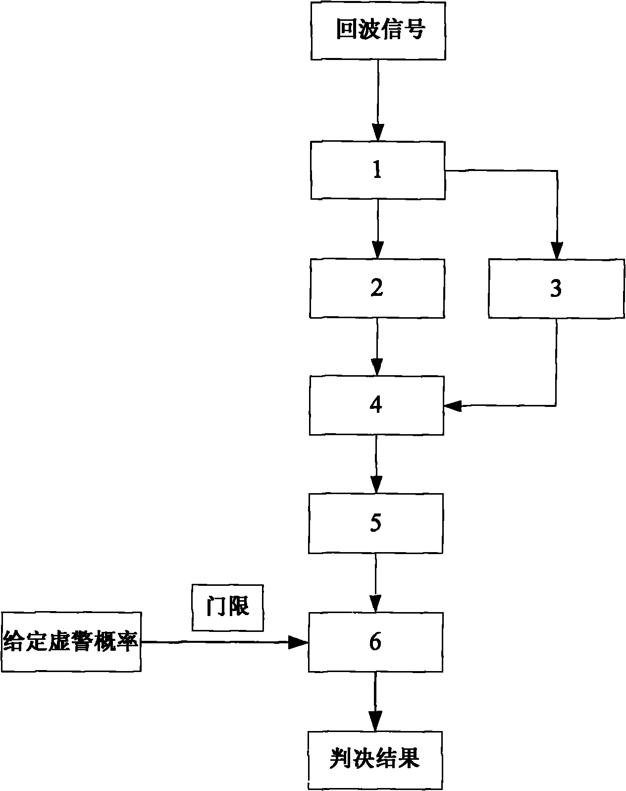
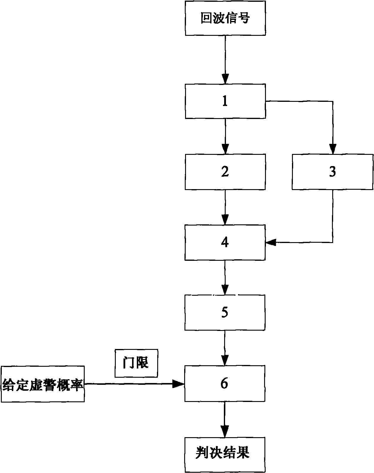
[0015] The present invention will be described in further detail below in conjunction with the accompanying drawings. With reference to the accompanying drawings in the description, the specific implementation of the present invention is divided into the following steps:

[0016] (1) After the signal returned from the radar antenna is amplified and mixed, it is sent to the computing device 1 to select echo data s(n) and delay data s(n-m).

[0017] (2) The computing device 2 receives the echo data s(n) from the computing device 1, completes FRFT, and obtains its modulus |F[s(n)]|.

[0018] (3) The calculation device 3 receives the delay data s(n-m) from the calculation device 1, completes FRFT, and calculates its modulus |F[s(n-m)]|.

[0019] (4) The calculation device 4 receives the output results of the calculation devices 2 and 3, and completes the operation |F[s(n)]|-F[s(n-m)]|.

[0020] (5) The calculation device 5 receives the output data of the calculation device 4 and...


PUM


Abstract

The invention discloses a moving target detector utilizing time delay FRFT mode difference, and the technology belongs to the field of radar signal processing. The existing moving target detection methods are mainly based on statistical models and fractal and modern signal processing technologies, and the methods have the weaknesses of a narrow range of applications, background clutter, unsatisfactory interference suppression, difficult implementation and the like. The maximum positive value of the FRFT mode difference between a received signal and a time delay signal thereof is adopted as the detection statistical quantity. The detector can suppress the interference and the clutter, improve the signal to noise ratio to a certain extent and effectively detect a moving target under the low signal to noise ratio. As the moving target detector is simple and easy to realize, the moving target detector can be applied in various reconnaissance and surveillance radar signal processing systems, and has the popularization and application value.

Description

1. Technical field [0001] The invention relates to a moving target detector using the time-delayed FRFT mode difference in the field of radar signal processing, which is suitable for signal processing systems of various imaging reconnaissance and early warning radars. 2. Background technology [0002] The effective detection of moving targets has always been a hot spot. The traditional method to deal with this problem is the detection method based on the statistical model of clutter. The first problem of this kind of method is to establish the statistical model of clutter. Later, some scholars took another approach and applied fractal theory to some clutter environments such as sea clutter that satisfy fractal characteristics. Generally, the target is detected by using the feature that the fractal dimension of the target echo is lower than that of the clutter echo. With the development of modern signal processing technology, modern signal processing technology has been wid...

Claims


Application Information

Patent Timeline
Patent Type & Authority Applications(China)
IPC IPC(8): G01S7/41G01S13/89
Inventor 关键李宝郭海燕
Owner NAVAL AERONAUTICAL & ASTRONAUTICAL UNIV PLA
Why Eureka
Try Eureka