Multifunctional strong shock simulating testing device and method

A technology of simulation test and impact device, which is applied in the direction of impact test, measuring device, machine/structural component test, etc., can solve the problems of many experiments, increased test cost, complicated tooling, etc., and achieve the effect of suppressing clutter

Inactive Publication Date: 2018-10-19
ZHONGBEI UNIV +1
View PDF5 Cites 11 Cited by
  • Summary
  • Abstract
  • Description
  • Claims
  • Application Information

AI Technical Summary

Problems solved by technology

The national military standard requires that the tested equipment should withstand sufficient times and strong axial impacts in the impact test, for example, it is required to perform at least three impacts in each of the two directions of each of the three orthogonal axes, and the number of experiments is large. Long time, complicated tooling, increased test cost

Method used


Image

  • Multifunctional strong shock simulating testing device and method
  • Multifunctional strong shock simulating testing device and method
  • Multifunctional strong shock simulating testing device and method

Examples


Embodiment 1

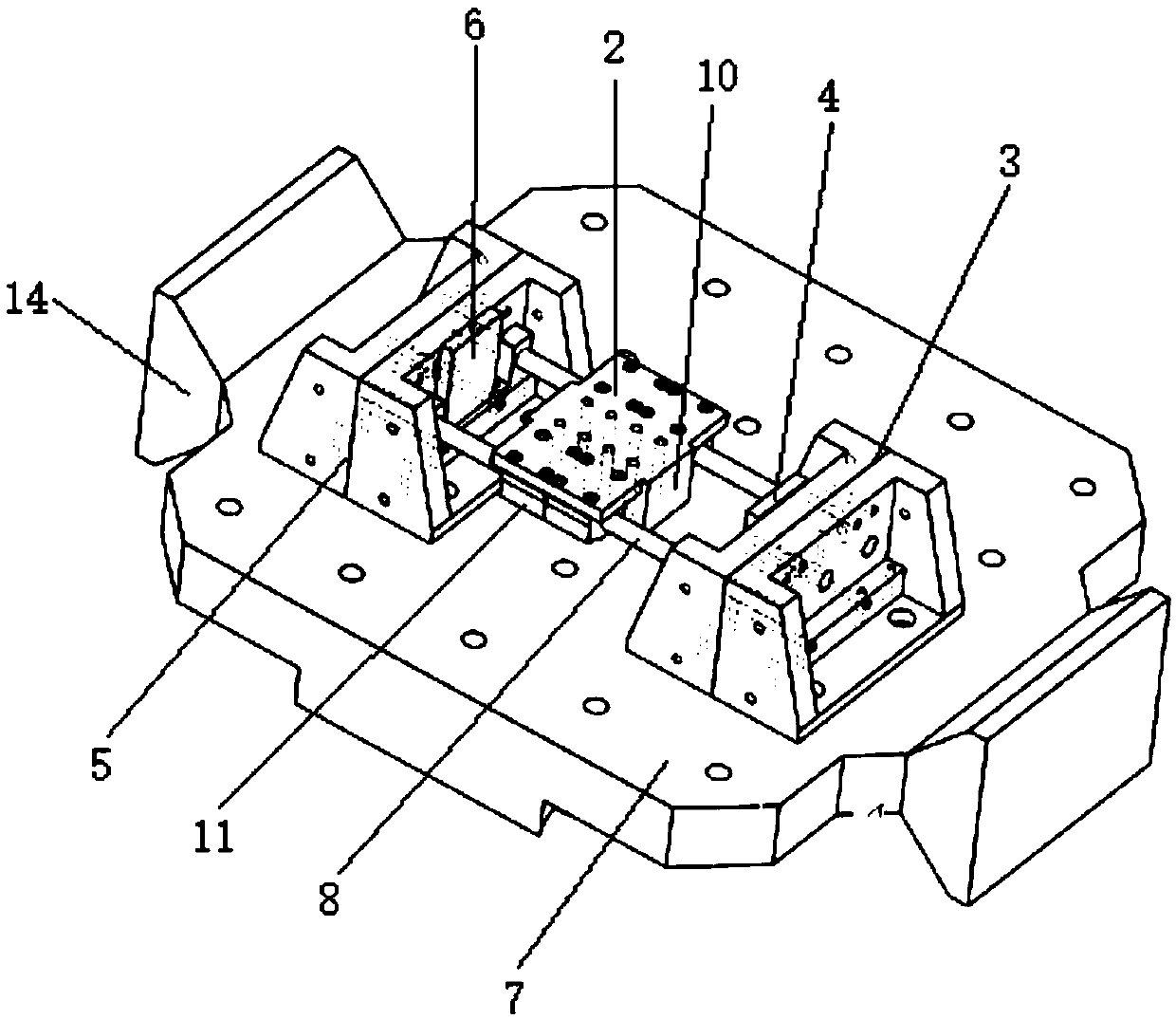
[0036] The invention provides a multifunctional strong impact simulation test device, the specific structure is as follows figure 1 and figure 2 As shown, it includes a power unit and a multifunctional strong impact device, and the multifunctional strong impact device includes a sliding work surface 2, a front baffle 3, a front baffle cushion 4, a rear baffle 5 and a rear baffle cushion 6; this implementation The power device in the example is an aerodynamic horizontal shock response spectrum impact table, and the front baffle 3 and the rear baffle 5 are installed on the shock response plate 7 of the aerodynamic horizontal shock response spectrum impact table. The aerodynamic horizontal shock response spectrum shock table in this embodiment is an existing device, and its specific structure will not be described here.

[0037]The front fender 3 and the rear fender 5 are arranged oppositely, the distance between the front fender 3 and the rear fender 5 is adjustable, and a pai...

Embodiment 2

[0054] Such as Figure 5 As shown, when the test conditions of the horizontal shock response spectrum table are not available, the power device includes a high-speed impact cylinder and a horizontal metal base 9, and an impact through hole is opened in the middle of the tailgate 5, and the high-speed impact cylinder includes an impact cylinder 12 and a cylinder piston rod 13. The impact cylinder 12, the rear baffle 5 and the front baffle 3 are successively installed on the horizontal metal base 9. There is a gap between the cylinder piston rod 13 and the rear baffle 5, and the cylinder piston rod 13 can be quickly extended under the air pressure. The impact head 10 goes out and passes through the impact through hole to collide with the impact head 10 of the sliding table 2 at a high speed.

[0055] The test method of the multifunctional strong impact simulation test device provided by the embodiment of the present invention 2 comprises the following steps:

[0056] Step 1: In...


PUM


Abstract

The invention discloses a multifunctional strong shock simulating testing device and method, and relates to the technical field of pneumatic shock equipment. The device comprises a power device, a sliding worktable top, a front baffle, a front baffle buffering cushion, a rear baffle and a rear baffle buffering cushion, wherein the front baffle and the rear baffle are oppositely arranged; a pair ofmutually-parallel slide rails is arranged between the front baffle and the rear baffle; each slide rail is sleeved with at least one linear slide block; the sliding worktable top is arranged on the linear slide blocks in a screwing manner; the front baffle buffering cushion and the rear baffle buffering cushion are correspondingly arranged at the inner side of the front baffle and the inner sideof the rear baffle. According to the multifunctional strong shock simulating testing device and method, a shock response spectrum shocking platform or a high-speed shock cylinder is used for supplyingshock power to the sliding worktable top, and thus twice classic shocks in positive direction and negative direction can be realized by once shocking, and the shock acceleration waveform can be amplified; and moreover, the classic shock and complex instantaneous shock in one direction can also be realized.

Description

technical field [0001] The invention relates to the technical field of pneumatic impact equipment, in particular to a multifunctional strong impact simulation test device and method. Background technique [0002] Weapons and some high-reliability electromechanical products and equipment have to withstand thousands of g of shock overload (g refers to the acceleration of gravity) during their working process. An important means of product and equipment reliability. [0003] At present, the pneumatic horizontal shock response spectrum shock table and the pendulum shock response spectrum horizontal shock table can generate complex shock shock acceleration waveforms through the impact of the energy weight on the shock acceleration table (shock response plate), which are often used to assess the shock response characteristics and Vibration and shock resistance. However, due to the slow speed of the energy weight hammer, the amplitude of the shock acceleration generated by hittin...

Claims


Application Information

Patent Timeline
Patent Type & Authority Applications(China)
IPC IPC(8): G01M7/08
Inventor 李波安晓红张亚李世中
Owner ZHONGBEI UNIV
Why Eureka
Try Eureka