
Electric connector and manufacturing method thereof

A technology for electrical connectors and manufacturing methods, which is applied in the direction of connection, manufacture of contact box/base, parts of connection devices, etc., can solve the problems of limiting the maximum transmission value of current, the fragile overall structure of the connector, etc., and achieve increased thickness and width effect

Active Publication Date: 2017-01-04
HESHAN DEREN ELECTRONIC TECH CO LTD
View PDF6 Cites 21 Cited by
  • Summary
  • Abstract
  • Description
  • Claims
  • Application Information

AI Technical Summary

Problems solved by technology

However, accommodating a large number of terminals in a limited space will not only make the overall structure of the connector fragile, but also limit the maximum transmission value of current

Method used


Image

  • Electric connector and manufacturing method thereof
  • Electric connector and manufacturing method thereof
  • Electric connector and manufacturing method thereof

Examples


Embodiment Construction

[0025] In order to facilitate the understanding of the present invention, the following describes the embodiments of the present invention in more detail with reference to the accompanying drawings and specific embodiments.

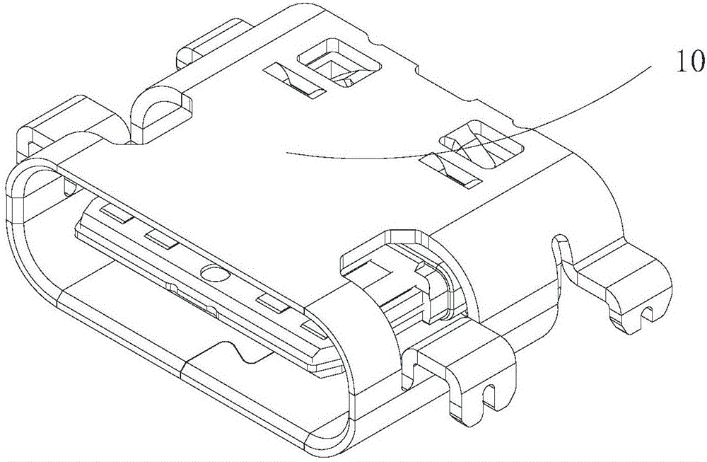
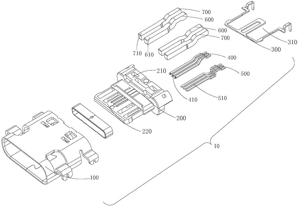
[0026] The embodiment of the present invention discloses an electrical connector, please refer to Figure 1-Figure 4 , An embodiment of the present invention provides an electrical connector 10, figure 1 Shows a perspective view of an electrical connector of an embodiment of the present invention, figure 2 A perspective exploded view of the electrical connector is shown. The connector includes a housing 100, an insulating body 200, a shielding plate 300, a first conductive terminal 400, a second conductive terminal 500, a power terminal 600, and a ground terminal 700.

[0027] The insulating body 200 includes a base 210 and a tongue 220 connected to the base.

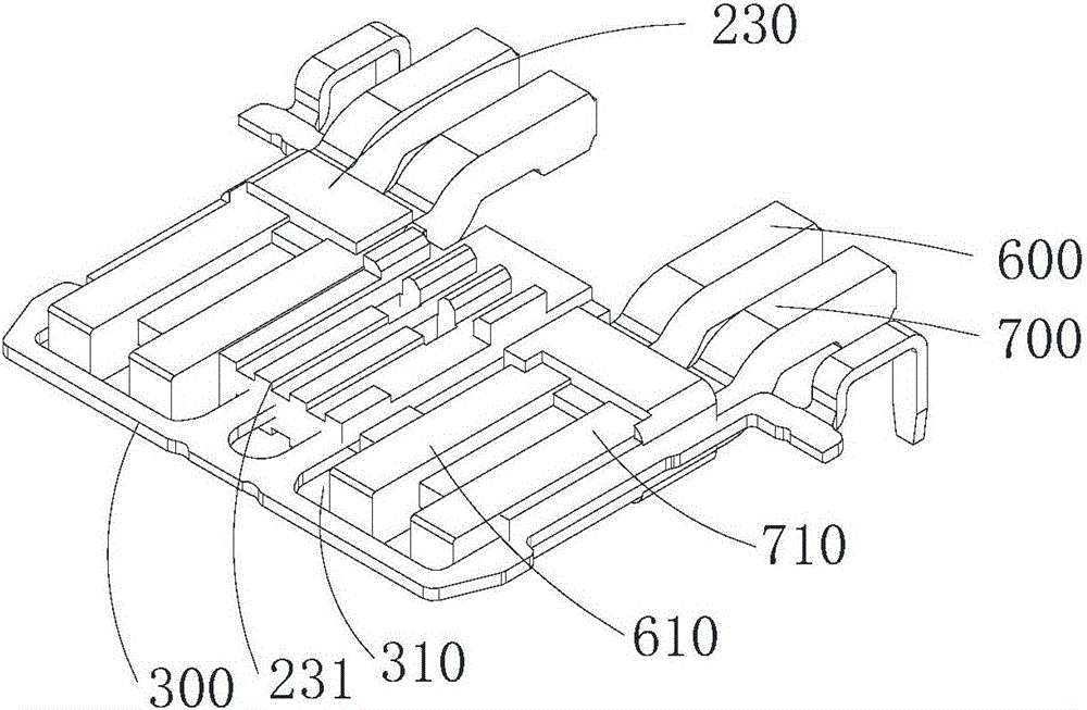
[0028] The shield plate 300 is embedded in the tongue plate 210, is located between the first conduct...


PUM

PropertyMeasurementUnit
Thicknessaaaaaaaaaa
Widthaaaaaaaaaa

Abstract

The embodiments of the invention disclose an electric connector and a manufacturing method thereof. The electric connector comprises an insulation body, a shielding plate, first conductive terminals, second conductive terminals, power supply terminals and grounding terminals, wherein the insulation body comprises a basal part and a tongue plate connected with the basal part; the shielding plate is embedded in the tongue plate, is disposed between the first conductive terminals and the second conductive terminals, and is provided with multiple accommodation grooves for accommodating the power supply terminals and the grounding terminals; contact portions of the first conductive terminals and contact portions of the second conductive terminals are respectively exposed on an upper surface and a lower surface of the tongue plate; and the power supply terminals and the grounding terminals are disposed at side edges of the first conductive terminals and the second conductive terminals, the power supply terminals comprise power supply contact portions, the grounding terminals comprise grounding contact portions, and two contact surfaces of each power supply contact portion and two contact surfaces of each grounding contact portion are respectively exposed on the upper surface and the lower surface of the tongue plate. Through such a mode, the electric connector provided by the embodiments of the invention can reinforce the overall structure of the electric connector and realizes a heavy-current function.

Description

Technical field [0001] The invention relates to the technical field of connectors, in particular to an electrical connector and a manufacturing method thereof. Background technique [0002] Nowadays, electronic devices are connected to an electronic computer through a variety of electrical connectors to perform data transmission, and a universal serial bus (USB) connector with a fast transmission speed is widely used. With the evolution of universal serial bus connector technology, a new type of universal serial bus connector has been developed, such as USBType-C based on the USB 3.1 specification, which has a slimmer design and faster transmission Speed ​​(up to 10Gbps) and more powerful power transmission (up to 100W). [0003] Another major feature of the USB Type-C connector is that it supports double-sided insertion of the USB interface. In order to meet the above requirements, in the standard USB Type-C connector specification, the multiple terminals of the connector are div...

Claims


Application Information

Patent Timeline
IPC IPC(8): H01R13/405H01R13/652H01R13/6581H01R43/18
CPCH01R13/405H01R13/652H01R13/6581H01R43/18
Inventor 邬彬
Owner HESHAN DEREN ELECTRONIC TECH CO LTD
Learn More