
Transverse differential protection method for DC power transmission line based on DC filter branch current

A technology of DC transmission lines and DC filters, applied in emergency protection circuit devices, electrical components, etc., can solve the problems of insufficient sensitivity, lack of setting basis, low sensitivity of main protection, etc., and achieve easy engineering implementation, low sampling rate requirements, The effect of improving performance

Active Publication Date: 2017-01-04
STATE GRID CORP OF CHINA +2
View PDF3 Cites 4 Cited by
  • Summary
  • Abstract
  • Description
  • Claims
  • Application Information

AI Technical Summary

Problems solved by technology

The main protection has low sensitivity and lack of setting basis. At the same time, the sampling frequency and processing capacity of the device are extremely high; the current differential protection action speed is too slow, it is difficult to quickly remove the fault, and the sensitivity to the high-impedance ground fault of the DC transmission line is insufficient. As a result, the protection performance cannot fully meet the actual needs of the project

Method used


Image

  • Transverse differential protection method for DC power transmission line based on DC filter branch current
  • Transverse differential protection method for DC power transmission line based on DC filter branch current
  • Transverse differential protection method for DC power transmission line based on DC filter branch current

Examples


Embodiment Construction

[0029] The technical solutions in the present invention will be clearly and completely described below in conjunction with specific embodiments and the accompanying drawings in the present invention.

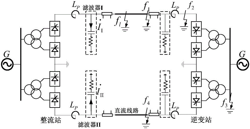
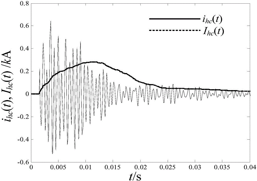
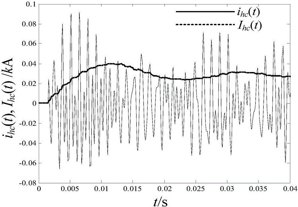
[0030] established as figure 1 As shown in the digital simulation model, write sampling algorithm (sampling rate 10kHz), sample and calculate relevant electrical quantity, carry out simulation to verify the performance of the present invention by setting different fault points and grounding short-circuit faults through different resistances.

[0031] During the simulation process, step 1, step 2, and step 3 of the present invention are executed sequentially in each sampling period, and the DC filter branch currents of one-side pole I and pole II of the direct current transmission system and the protection transverse differential current are calculated respectively. RMS value. When the transverse differential current and the timing time meet the conditions of formula (2) and for...


PUM


Abstract

The invention discloses a transverse differential protection method for a DC power transmission line based on a DC filter branch current, and the method comprises the steps: 1, measuring current instantaneous values, passing through an I-pole DC filter branch circuit and an II-pole DC filter branch circuit, of a rectification side of a DC power transmission system, and recording the current instantaneous values as i(t) and i<II>(t); 2, calculating a transverse differential protection current instantaneous value according to a formula: i<hc>(t) = i(t) + i<II>(t), taking 10 ms as a data window, calculating a transverse differential current, the root-mean-square value of the I-pole DC filter branch circuit and the root-mean-square value of the II-pole DC filter branch circuit, and respectively recording the transverse differential current, the root-mean-square value of the I-pole DC filter branch circuit and the root-mean-square value of the II-pole DC filter branch circuit as I<hc>, I, and I<II>; 3, carrying out the fault discrimination: start timing from zero when I<hc> is greater than I<set>, and recording a timing result as t; setting a mark flag = 1 if t is greater than t<set>, judging that a DC power transmission line region has a fault at this moment, and executing step 4, wherein I<set> is a current operation set value, and t<set> is a time delay set value; 4, carrying out the discrimination of a fault region: judging that the fault happens in a I-pole line region if I / I<II> is greater than one, or else, judging that the fault happens in an II-pole line region.

Description

technical field [0001] The invention relates to the technical field of relay protection and automatic control of a power system, in particular to a method for protecting DC transmission line transverse differences based on DC filter branch current. Background technique [0002] With the rapid development of DC transmission technology in my country in recent years, a large number of EHV and UHV DC transmission projects have been put into operation, and the AC-DC hybrid grid has gradually replaced the traditional AC grid and has become an important feature of the current domestic grid. [0003] In the DC transmission system, the working conditions of the DC transmission line are harsh and the probability of failure is high. Therefore, configuring a high-performance relay protection system is an important prerequisite to ensure the safe and reliable operation of the DC transmission system. At present, most DC transmission lines use traveling wave protection and differential und...

Claims


Application Information

Patent Timeline
IPC IPC(8): H02H7/26
CPCH02H7/268
Inventor 张侃君尹项根陈堃戚宣威胡伟张时耘文博黎恒烜杜镇安雷杨叶庞琪王婷
Owner STATE GRID CORP OF CHINA
Learn More