
Security monitoring device, security monitoring system and security monitoring method

A security monitoring and equipment technology, which is applied to closed-circuit television systems, televisions, electrical components, etc., can solve the problems of inconvenient installation of wireless security monitoring equipment, inconvenient installation of wired security monitoring equipment, and large power consumption of cameras, and achieves a high level of power consumption. The effect of long standby time, fast startup speed and convenient installation

Inactive Publication Date: 2017-01-04
SHENZHEN AONI ELECTRONICS IND
View PDF4 Cites 25 Cited by
  • Summary
  • Abstract
  • Description
  • Claims
  • Application Information

AI Technical Summary

Problems solved by technology

[0003] Wired security monitoring equipment needs to be connected to the display terminal and the power supply terminal by wire, so that network wiring and power wiring are required when installing wired security monitoring equipment. Therefore, the installation of wired security monitoring equipment is inconvenient and low in installation efficiency.
At the same time, wireless security monitoring equipment needs to capture video data information in the monitoring range and transmit the video data information to the outside through the wireless network, so that the power consumption of the wireless network camera is large. Therefore, most wireless security monitoring equipment is powered by a power adapter
Therefore, the installation of wireless security monitoring equipment still requires power wiring, so that the installation of wireless security monitoring equipment still has problems such as inconvenient installation and low installation efficiency.

Method used


Image

  • Security monitoring device, security monitoring system and security monitoring method
  • Security monitoring device, security monitoring system and security monitoring method
  • Security monitoring device, security monitoring system and security monitoring method

Examples


Embodiment Construction

[0033] In order to make the object, technical solution and advantages of the present invention clearer, the present invention will be further described in detail below in conjunction with the accompanying drawings and embodiments. It should be understood that the specific embodiments described here are only used to explain the present invention, not to limit the present invention.

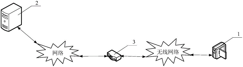
[0034] Figure 1 ~ Figure 2 An embodiment of the security monitoring system of the present invention is shown. In this example, if figure 1 As shown, the security monitoring system includes a security monitoring device 1 and a server 2 . The security monitoring device 1 is communicatively connected with the server 2 through a communication link. Wherein, the communication link includes router 3 . The router 3 is connected to the server 2 via a wired network or a wireless network. The router 3 is connected to the security monitoring device 1 through a wireless network communication. Wherein, t...


PUM


Abstract

The invention discloses a security monitoring device, a security monitoring system and a security monitoring method. The security monitoring device comprises: an auxiliary power supply circuit used for supplying power to an MCU, a WIFI module and a PIR human body infrared sensor. The MCU is used for closing a main power supply circuit, and the security monitoring device is in a dormant state. The PIR human body infrared sensor is used for notifying the MCU to open the main power supply circuit when a human body is detected in a caution area, and the main power supply circuit supplies power to a video information acquisition module and converts from the dormant state into an awake state. The video information acquisition module is used for acquiring video data information and sending the video data information to the outside by the WIFI module. The MCU is further used for closing the main power supply circuit and converting from the awake state into the dormant state after the video data information is sent. When the PIR human body infrared sensor detects the human body, the conversion of the dormant state and the awake state is realized, and the technical effects of reducing the power consumption and prolonging the standby time are realized.

Description

technical field [0001] The invention relates to the field of security technology, in particular to a security monitoring device, a security monitoring system and a security monitoring method. Background technique [0002] With the improvement of people's living standards, the needs of users for security are also increasing. Therefore, in recent years, many companies have begun to set foot in the security market, and various wired security monitoring equipment and wireless security monitoring equipment have appeared on the market. [0003] Wired security monitoring equipment needs to be connected to the display terminal and the power supply terminal by wire, so that network wiring and power wiring are required when installing wired security monitoring equipment. Therefore, the installation of wired security monitoring equipment is inconvenient and low in installation efficiency. At the same time, wireless security monitoring equipment needs to capture video data information ...

Claims


Application Information

Patent Timeline
Patent Type & Authority Applications(China)
IPC IPC(8): H04N7/18
CPCH04N7/18H04N7/181
Inventor 吴世杰张静黄海健吴文健
Owner SHENZHEN AONI ELECTRONICS IND
Learn More