Beam recognition method and system and network node

A network node and identification method technology, which is applied in network planning, wireless communication, electrical components, etc., can solve the problem of increasing downlink synchronization and identifying process delays for optimal beams, affecting the access speed of terminals to high-frequency sites, and preventing terminals from Issues such as identifying optimal beams

Inactive Publication Date: 2017-01-04
ZTE CORP
View PDF3 Cites 19 Cited by
  • Summary
  • Abstract
  • Description
  • Claims
  • Application Information

AI Technical Summary

Problems solved by technology

For terminals without any prior information, this will greatly increase the time delay of downlink synchronization and identification of the optimal beam, which will seriously affect the access speed of the terminal to the high-frequency site; The complexity of identification reduces the accuracy of identification, and even causes the terminal to fail to identify the optimal beam
[0007] The above-mentioned technical problems do not provide a feasible solution for beam identification based on high-frequency communication in the prior art

Method used


Image

  • Beam recognition method and system and network node
  • Beam recognition method and system and network node
  • Beam recognition method and system and network node

Examples


Embodiment Construction

[0098] In order to make the purpose, technical solution and advantages of the present invention more clear, the embodiments of the present invention will be described in detail below in conjunction with the accompanying drawings. It should be noted that, in the case of no conflict, the embodiments in the present application and the features in the embodiments can be combined arbitrarily with each other.

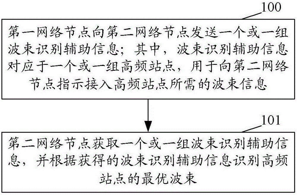
[0099] figure 1 It is a flowchart of the beam identification method of the present invention, such as figure 1 As shown, for the first network node side, at least include:

[0100] Step 100: The first network node sends one or a set of beam identification auxiliary information to the second network node; wherein, the beam identification auxiliary information corresponds to one or a group of high-frequency sites, and is used to indicate to the second network node to access high-frequency Beam information required by the site.

[0101] Wherein, the first network node include...


PUM


Abstract

The invention discloses a beam recognition method, a beam recognition system and a network node. The method beam recognition comprises the steps that: a first network node sends one or a group of beam recognition auxiliary information to a second network node, wherein the beam recognition auxiliary information corresponds to one or a group of high-frequency sites and is used for indicating beam information required for accessing the high-frequency site to the second network node; and the second network node obtains the one or a group of beam recognition auxiliary information, and recognizes an optimal beam of the high-frequency site according to the obtained beam recognition auxiliary information. By adopting the beam recognition method, the beam recognition system and the network node, since the second network node obtains the beam recognition auxiliary information required in the beam recognition process, the detection range in the access process is reduced; in addition, when compared with the method of accessing the high-frequency site through blind test, the complexity of optimal beam recognition is reduced, the time delay in the optimal beam recognition process is shortened, and further the access rate to the high-frequency site is increased.

Description

technical field [0001] The present invention relates to a long term evolution advanced system (LTE-Advanced, Long term evolution advanced system), in particular to a high-frequency communication-based beam identification method, system and network node. Background technique [0002] With the continuous development of radio technology, a large number of various radio services have emerged, and the spectrum resources on which radio services rely are limited. Facing the continuous increase in people's demand for bandwidth, traditional commercial communications mainly use 300MHz~3GHz Spectrum resources are extremely tense, which cannot meet the needs of future wireless communications. [0003] In the future wireless communication, carrier frequencies higher than those used in the fourth generation (4G) communication system will be used for communication, such as 28GHz, 45GHz, etc. This high-frequency channel has a large free propagation loss, The shortcomings of being easily ab...

Claims


Application Information

Patent Timeline
Patent Type & Authority Applications(China)
IPC IPC(8): H04W16/28
CPCH04W16/28
Inventor 刘星毕峰刘文豪苗婷郁光辉
Owner ZTE CORP
Why Eureka
Try Eureka