High speed placement head

A chip head, high-speed technology, applied in the direction of printed circuit, electrical components, printed circuit manufacturing, etc., can solve the problems of complex manufacturing process, expensive equipment, high manufacturing cost, and achieve the effect of eliminating restlessness, reducing quantity and running smoothly

Active Publication Date: 2019-01-25
广东木几智能装备有限公司
View PDF11 Cites 0 Cited by
  • Summary
  • Abstract
  • Description
  • Claims
  • Application Information

AI Technical Summary

Problems solved by technology

However, this kind of complex structure, complex manufacturing process, high manufacturing cost, resulting in high cost of the whole equipment

Method used


Image

  • High speed placement head
  • High speed placement head
  • High speed placement head

Examples


Embodiment Construction

[0020] The specific embodiments of the present invention will be further described below in conjunction with the drawings:

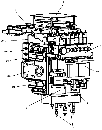
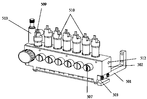
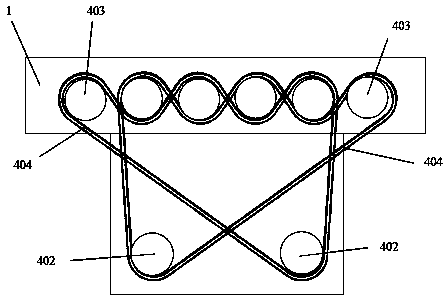
[0021] Such as Figure 1-Figure 5 As shown, a high-speed placement head includes a placement head holder 1, a plurality of placement axes installed in the placement head holder 1, a Z-direction lifting mechanism that drives the placement axis 2 up and down, and a drive placement axis 2 Circumferentially rotating R-direction angle mechanism 4, adjust the placement axis 2 vacuum module 5 for sucking and reclaiming, the upper back of the placement head bracket 1 is equipped with an integrated control module 6, and the upper front of the placement head bracket 1 is installed Vacuum module 5, the middle front of the placement head bracket 1 is equipped with an R-direction stepping motor 401 that drives the R-direction angle mechanism 4 and a CCD camera 7 that collects images. The back of the placement head bracket 1 is equipped with two rows of Z-directions. Th...


PUM


Abstract

The invention provides a high-speed chip mounting head, which comprises a mounting head bracket, a plurality of chip mounting shafts installed in the mounting head bracket, a Z-direction lifting mechanism, an R-direction turning mechanism and a vacuum module, and is characterized in that the reverse side of the upper part of the mounting head bracket is provided with an integrated control assembly, the obverse side of the upper part of the mounting head bracket is provided with the vacuum module, the middle part of the obverse side of head mounting bracket is provided with an R-direction stepping motor used for driving the R-direction turning mechanism and a CCD camera used for acquiring images, the reverse side of the head mounting bracket is provided with an upper row of Z-direction driving motors and a lower-row of Z-direction driving motors, and output shafts of the Z-direction driving motors are perpendicular to a Z-axis. The beneficial effects are that the integrated control assembly is installed on the chip mounting head, and each suction nozzle uses a single vacuum suction pipe, so that suction control is more stable; an air pressure detection integrated module is installed at the bottom, negative pressure is directly connected to a converging and assembling board, and an external circuit is simple; and miniaturization and lightening of the chip mounting head are facilitated.

Description

Technical field [0001] The invention relates to a patch head, especially a high-speed patch head. Background technique [0002] The use of high-speed mounting technology to install integrated circuit components on PCB boards is an important way to improve installation efficiency and installation accuracy. The placement head is one of the most critical equipment of the placement machine, which directly affects the speed and accuracy of placement. [0003] At present, the placement heads used in foreign high-speed placement machines are usually composed of placement shafts, linear bearings, jackets, timing belt wheels, bearings, servo motors, etc. The placement shafts are made of spline shafts, and the outside is symmetrical. The two arc grooves and the balls in the linear bearing are matched and connected to realize infinite linear movement up and down; the linear bearing and a pair of deep groove ball bearings installed on it are installed in the casing together, and the linear be...

Claims


Application Information

Patent Timeline
Patent Type & Authority Patents(China)
IPC IPC(8): H05K3/30
CPCH05K3/30H05K2203/085H05K2203/163
Inventor 吴志达程治国吴凡
Owner 广东木几智能装备有限公司
Why Eureka
Try Eureka