Steam valve, upper cover and cooking appliance

A technology for cooking utensils and steam valves, which is applied in the directions of cooking utensil lids, cooking utensils, household utensils, etc., can solve the problems of increasing the thickness of the lid of an electric rice cooker, reducing the use comfort of the product, increasing the overall weight of the lid, and achieving a compact structure, The effect of reducing consumables and weight

Active Publication Date: 2017-01-11
FOSHAN SHUNDE MIDEA ELECTRICAL HEATING APPLIANCES MFG CO LTD +1
View PDF6 Cites 9 Cited by
  • Summary
  • Abstract
  • Description
  • Claims
  • Application Information

AI Technical Summary

Problems solved by technology

[0002] At present, the valve seat of the steam valve of the existing electric cooker is connected with the valve cover to form an independent part. In the existing electric cooker, in order to ensure the installation stability of the steam valve, it is usually used to increase the distance between the cover of the electric cooker and the steam valve. The way of assembling the area between them, that is, there is an installation groove formed on the surface cover of some existing rice cooker lids, and the steam valve is fixed by snapping the steam valve into the installation groove, but the setting of this structure is relatively increased. The thickness of the lid of the rice cooker is increased, which leads to an increase in the cost of the product, and this also increases the overall weight of the lid, which makes the rice cooker vibrate easily due to the increase in the inertial force of the lid during the opening of the lid, resulting in The possibility of food splashing increases, which reduces the comfort of the product and is not conducive to the marketing of the product

Method used


Image

  • Steam valve, upper cover and cooking appliance
  • Steam valve, upper cover and cooking appliance
  • Steam valve, upper cover and cooking appliance

Examples


Embodiment Construction

[0053] In order to understand the above-mentioned purpose, features and advantages of the present invention more clearly, the present invention will be further described in detail below in conjunction with the accompanying drawings and specific embodiments. It should be noted that, in the case of no conflict, the embodiments of the present application and the features in the embodiments can be combined with each other.

[0054] In the following description, many specific details are set forth in order to fully understand the present invention. However, the present invention can also be implemented in other ways different from those described here. Therefore, the protection scope of the present invention is not limited by the specific details disclosed below. EXAMPLE LIMITATIONS.

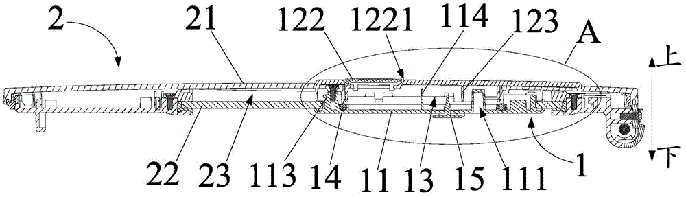
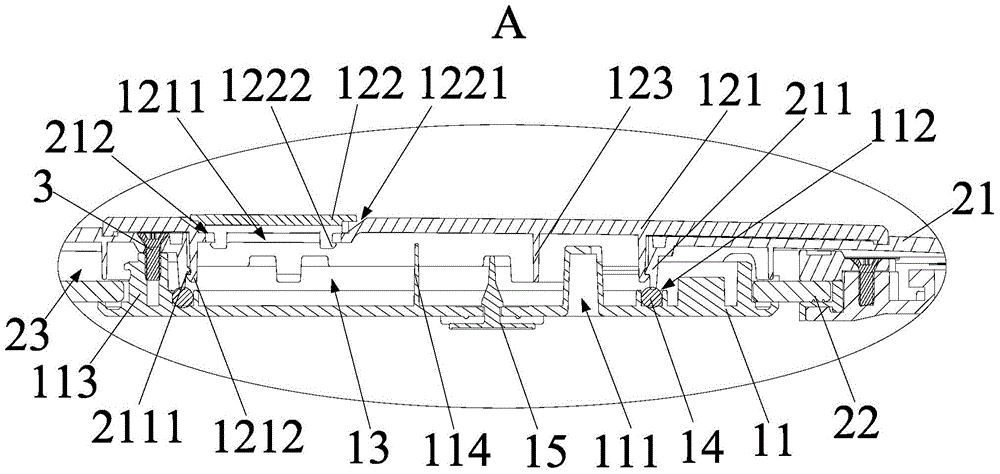
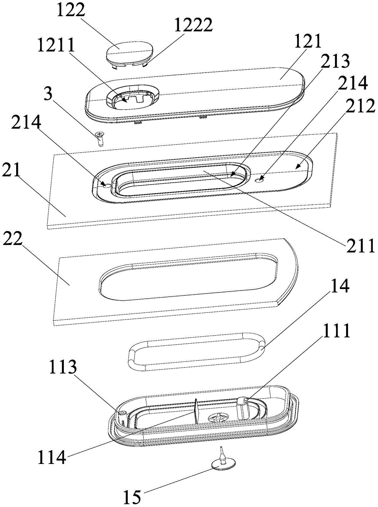
[0055] Refer below Figure 1 to Figure 6 The steam valve 1 and the upper cover 2 according to some embodiments of the present invention are described.

[0056] Such as Figure 1 to Figure 6 As sho...


PUM


Abstract

The invention provides a steam valve, an upper cover and a cooking appliance, wherein the steam valve comprises a valve seat and a valve cover; a steam inlet is formed in the valve seat; the valve seat is arranged on an inner cover and the valve seat is in sealing connection to a surface cover; a steam outlet is formed in the valve cover; the valve cover is arranged on the surface cover; and the valve cover and the valve seat are relatively arranged, and a steam passage is formed, wherein the steam passage communicates with the steam inlet and the steam outlet. According to the steam valve provided by the invention, under the condition of achieving the functions of preventing spillover and discharging steam of the finished product (the steam valve), the valve seat of the steam valve is arranged on the inner cover of the upper cover and the valve seat is in sealing connection to the surface cover, so that stable installation between the valve seat and the upper cover is achieved under the precondition of not increasing an assembly area between the upper cover and the steam valve; and meanwhile, the upper cover is more compact in structure, so that the overall thickness of the upper cover is reduced, the weight of the upper cover is reduced and consumables of the upper cover are reduced.

Description

technical field [0001] The invention relates to the field of kitchen appliances, in particular to a steam valve, an upper cover with the steam valve and a cooking appliance with the upper cover. Background technique [0002] At present, the valve seat of the steam valve of the existing electric cooker is connected with the valve cover to form an independent part. In the existing electric cooker, in order to ensure the installation stability of the steam valve, it is usually used to increase the distance between the cover of the electric cooker and the steam valve. The way of assembling the area between them, that is, there is an installation groove formed on the surface cover of some existing rice cooker lids, and the steam valve is fixed by snapping the steam valve into the installation groove, but the setting of this structure is relatively increased. The thickness of the lid of the rice cooker is increased, which leads to an increase in the cost of the product, and this a...

Claims


Application Information

Patent Timeline
Patent Type & Authority Applications(China)
IPC IPC(8): A47J27/00A47J27/08A47J36/00A47J36/06
Inventor 林毅詹兴龚圆杰罗志晓黄韦铭梁志佳李新宇
Owner FOSHAN SHUNDE MIDEA ELECTRICAL HEATING APPLIANCES MFG CO LTD
Why Eureka
Try Eureka