Clamp

A fixture and splint technology, applied in the direction of clamping, clamping devices, manufacturing tools, etc., can solve the problems of large clamping errors on the outer surface of products, difficulty in ensuring the processing accuracy of high-brightness C angles, and reduced processing efficiency.

Inactive Publication Date: 2017-01-11
YULONG COMPUTER TELECOMM SCI (SHENZHEN) CO LTD
View PDF9 Cites 2 Cited by
  • Summary
  • Abstract
  • Description
  • Claims
  • Application Information

AI Technical Summary

Problems solved by technology

[0002] At present, the high-brightness C angle is widely used on metal battery covers and other products, basically covering more than 95% of the products, and in order to obtain a delicate appearance, the clamping device plays a very critical role, but in the prior art, When processing a product (such as a metal battery cover) with a high-brightness C-angle, the product is generally placed on the pallet, and then a pressure plate is set above the pallet, and then the pressure plate is driven by the driving device to press the product on the pallet. Between the clamping method and the pressure plate, the installation reference plane of this clamping method is the inner surface of the product and the upper surface of the base, but the actual surface to be processed is the outer surface of the product, so that the surface to be processed of the product is inconsistent with the reference plane of installation and positioning , so the installation accura

Method used


Image

  • Clamp
  • Clamp
  • Clamp

Examples


Embodiment Construction

[0041] In order to understand the above-mentioned purpose, features and advantages of the present invention more clearly, the present invention will be further described in detail below in conjunction with the accompanying drawings and specific embodiments. It should be noted that, in the case of no conflict, the embodiments of the present application and the features in the embodiments can be combined with each other.

[0042] In the following description, many specific details are set forth in order to fully understand the present invention. However, the present invention can also be implemented in other ways different from those described here. Therefore, the protection scope of the present invention is not limited by the specific details disclosed below. EXAMPLE LIMITATIONS.

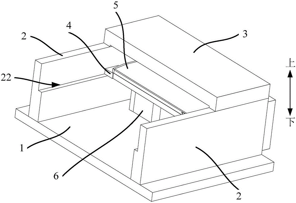
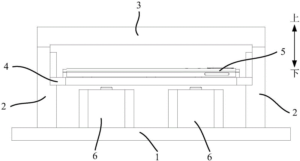
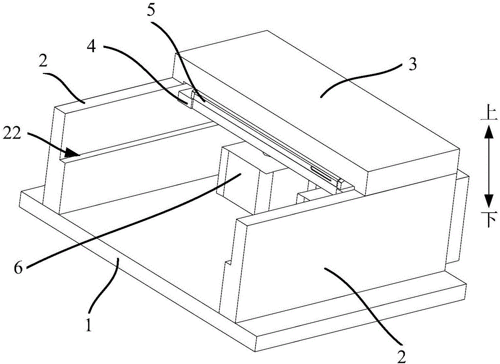
[0043] Refer below Figure 1 to Figure 5 Clamps according to some embodiments of the invention are described.

[0044] Such as Figure 1 to Figure 5 As shown, the embodiment of the first aspect of...


PUM


Abstract

The invention provides a clamp, which is used for clamping a to-be-processed part, and comprises a base, two clamping plates, a pressing plate, a supporting plate and a first driving device, wherein the two clamping plates are arranged on the base in a spaced manner; the pressing plate is arranged above the base, and two oppositely arranged ends of the pressing plate are separately connected to the two clamping plates; the supporting plate is arranged between the base and the pressing plate and is used for holding the to-be-processed part; and the first driving device is connected with the supporting plate, and is used for driving the supporting plate to drive the to-be-processed part to move to be attached to the pressing plate. When the to-be-processed part is clamped by the clamp provided by the technical scheme, as the pressing plate is fixed, the face, near the base, of the pressing plate and the face, far away from the support plate, of the to-be-processed part are installation reference planes, while for the to-be-processed part, such as a metal battery cover and the like, the upper surface of the to-be-processed part is a to-be-processed surface when a highlight C corner is processed, so that the installation reference planes are consistent with the to-be-processed surface, and therefore, the installation accuracy of the to-be-processed surface of the to-be-processed part, such as a metal battery cover and the like, can be increased, the accuracy of the processed highlight C corner can be further ensured, and the aesthetic property of the to-be-processed part, such as a metal battery cover and the like, can be improved.

Description

technical field [0001] The invention relates to the field of processing technologies such as mobile phone accessories, in particular to a clamp. Background technique [0002] At present, the high-brightness C angle is widely used on metal battery covers and other products, basically covering more than 95% of the products, and in order to obtain a delicate appearance, the clamping device plays a very critical role, but in the prior art, When processing a product (such as a metal battery cover) with a high-brightness C-angle, the product is generally placed on the pallet, and then a pressure plate is set above the pallet, and then the pressure plate is driven by the driving device to press the product on the pallet. Between the clamping method and the pressure plate, the installation reference plane of this clamping method is the inner surface of the product and the upper surface of the base, but the actual surface to be processed is the outer surface of the product, so that t...

Claims


Application Information

Patent Timeline
IPC IPC(8): B23Q3/08
CPCB23Q3/08B23Q2703/04
Inventor 刘霆锋冀方冉
Owner YULONG COMPUTER TELECOMM SCI (SHENZHEN) CO LTD
Why Eureka
Try Eureka