Eureka AIR delivers breakthrough ideas for toughest innovation challenges, trusted by R&D personnel around the world.

Battery installation structure and power supply equipment

A technology for mounting structures and batteries, which is applied in the direction of electric power devices, power devices, transportation and packaging, etc., and can solve problems such as easy cracking of the mounting holes of the mounting plate and poor heat dissipation of the battery

Active Publication Date: 2017-01-11
CHERY AUTOMOBILE CO LTD
View PDF5 Cites 3 Cited by
  • Summary
  • Abstract
  • Description
  • Claims
  • Application Information

AI Technical Summary

Problems solved by technology

[0006] In order to solve the problem that the mounting hole of the mounting plate is easy to crack and the heat dissipation effect of the battery is poor, the embodiment of the present invention provides a battery mounting structure and a power supply device

Method used


Image

  • Battery installation structure and power supply equipment
  • Battery installation structure and power supply equipment
  • Battery installation structure and power supply equipment

Examples


Embodiment Construction

[0036] In order to make the object, technical solution and advantages of the present invention clearer, the implementation manner of the present invention will be further described in detail below in conjunction with the accompanying drawings.

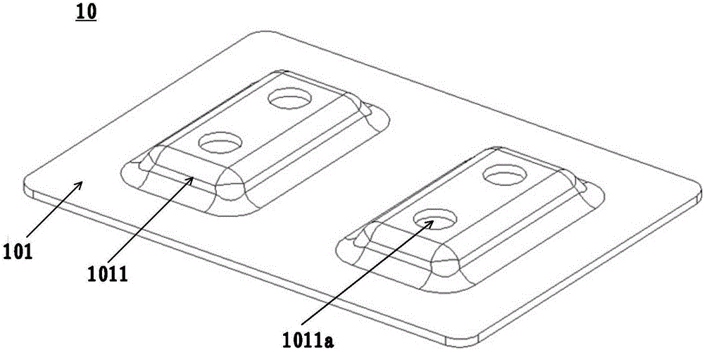
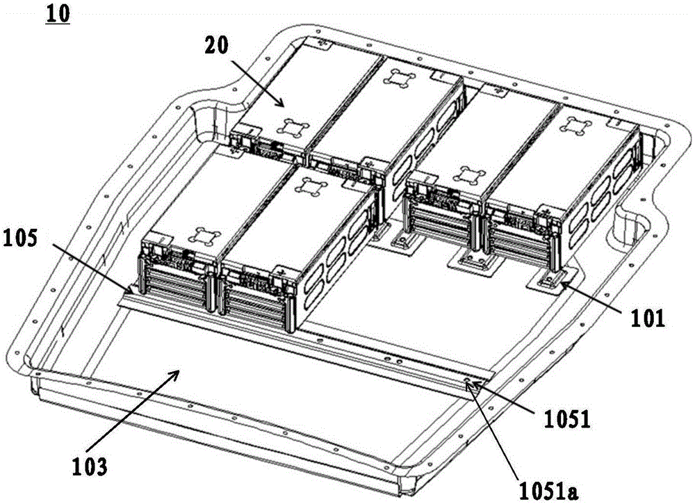
[0037] Such as figure 1 As shown, the embodiment of the present invention provides a battery installation structure 10 , and the battery installation structure 10 may include: a first installation board 101 .

[0038] A plurality of first bosses 1011 are formed on the first mounting plate 101 through a stamping process, and each first boss 1011 is provided with a mounting hole 1011a, and the battery can be mounted on the first boss 1011 through the mounting hole 1011a.

[0039] In summary, in the battery mounting structure provided by the embodiment of the present invention, a plurality of bosses are formed on the first mounting plate through a stamping process, mounting holes are provided on the bosses, and then the battery can be ins...


PUM


Abstract

The invention discloses a battery installation structure and a power supply equipment, which belongs to the car manufacturing. The battery installation structure as mentioned includes the first mounting plate; by stamping technology, several first lug bosses which are provided with mounting holes forms on the first mounting plate, and the battery is installed on the first lug boss through the mounting holes. The power supply equipment as mentioned includes the battery and its installation structure. The battery is installed in the battery installation structure. By designing a battery installation structure, this invention which is used in the battery installation solves the problems that the battery mounting plate is likely to crack and the heat dissipation of battery is worse, enhances the rigidity and strength of the battery installation structure and is beneficial for the battery heat dissipation which can reduce some potential safety hazards.

Description

technical field [0001] The invention relates to the field of automobile manufacturing, in particular to a battery installation structure and a power supply device. Background technique [0002] With the depletion of oil resources and the improvement of people's awareness of environmental protection, new energy vehicles will become the mainstream of the development of the automobile industry in the first few decades of the new century. Among new energy vehicles, hybrid vehicles have the advantages of low emissions of pure electric vehicles and It makes up for the shortcoming of pure electric vehicles with short continuous mileage, so it has been paid more and more attention. However, how to install the batteries of hybrid electric vehicles is a key issue in the manufacturing process of hybrid electric vehicles. [0003] In the prior art, there are usually multiple batteries in a hybrid vehicle, which are generally installed on a mounting plate. Usually, a plurality of mountin...

Claims


Application Information

Patent Timeline
Patent Type & Authority Applications(China)
IPC IPC(8): B60K1/04
CPCB60K1/04B60K2001/0438
Inventor 董宗岐刘丽丽
Owner CHERY AUTOMOBILE CO LTD
Why Eureka
Eureka Blog
Learn More