
Wet Tape Machine

A tape machine and wet water technology, applied in the direction of sending objects, thin material handling, transportation and packaging, etc., can solve the problems of low work efficiency, operator danger, easy injury and human hands, etc., to achieve convenient push and pull, ensure reliability and The effect of accuracy

Active Publication Date: 2018-01-23
浙江具心科技有限公司
View PDF6 Cites 0 Cited by
  • Summary
  • Abstract
  • Description
  • Claims
  • Application Information

AI Technical Summary

Problems solved by technology

When sticking and sealing the tape, it is generally used to cut off tape strips of different lengths from the tape roll by using sharp scissors or blades by hand. In the process of cutting the tape strips and cleaning the knife edge, it is time-consuming and labor-intensive for the operator, and it is easy to injure the hands and bring danger to the operator, and use sharp scissors or blades and other sharp tools for a long time. The edge of the knife is easy to stick to the glue on the tape, making the edge of the knife unsharp or even causing damage, which affects the service life; second, in the operation of manually cutting the tape, whether the length of the continuously cut tape strips is the same or tapes of different lengths When cutting a tape strip, the length of the tape strip to be cut must be repeatedly measured, which makes the work efficiency low, and the length of the cut tape strip cannot be very accurate, resulting in waste of tape, which is not conducive to large-scale operations. Ideal for cutting tape jobs that require switching between strips of different lengths

Method used


Image

  • Wet Tape Machine
  • Wet Tape Machine
  • Wet Tape Machine

Examples


Embodiment Construction

[0044] The present invention will be further described in detail below in conjunction with the accompanying drawings and embodiments.

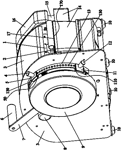
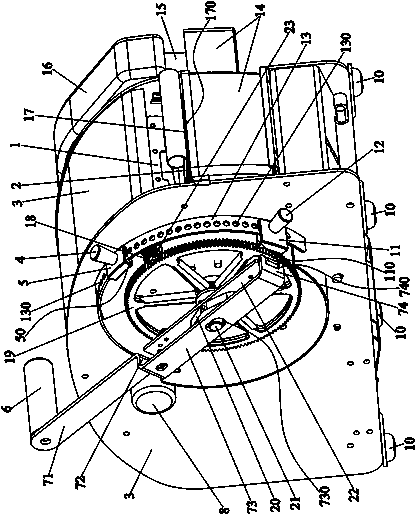
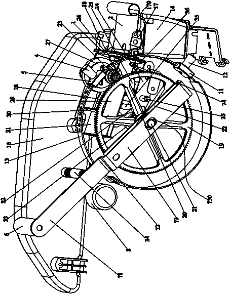
[0045] Wet water tape machine, such as Figure 1-19 As shown, it includes the casing 3, the tape reel 34 fixedly arranged on the rear side of the casing 3, the tape reel fixedly sleeved in the tape reel 34, and the first one fixedly arranged in the casing 3 and positioned at the front side of the tape reel 34. A pallet 28, near the front end of the first pallet 28 and the second pallet 17 opposite to the front end of the first pallet 28, is fixedly connected on the first pallet 28 and the tape strip 43 in the tape roll is removed from the first pallet. Plate 28 is guided to the traction guide belt mechanism of the second pallet 17, the cutter 1 that can move up and down is fixedly arranged between the first pallet 28 and the second pallet 17 and the tape strip 43 is cut off, and is fixedly arranged on the The front of the second pallet 17 and...


PUM


Abstract

The invention discloses a wet water tape machine. The wet water tape machine comprises a machine shell, a tape reel, a tape roll, a first supporting plate, a second supporting plate, a pulling and tape guiding mechanism, a cutter, a water smearing mechanism, a drive shaft, a pushing and pulling rod and a tape length locating mechanism, wherein the pushing and pulling rod is arranged at one end of the drive shaft and drives the drive shaft to rotate, and the tape length locating mechanism is fixedly arranged on the outer side face of the machine shell and located on the inner side of the pushing and pulling rod. The wet water tape machine adopts tape conveying, tape cutting and tape water smearing integrated assembly line arrangement, through linkage operation of the tape reel, the pushing and pulling rod, the tape length locating mechanism, the pulling and tape guiding mechanism, the cutter and the water smearing mechanism which are arranged in the machine shell, the tape is conveyed, cut and smeared with water in the machine shell, and tape strips are sent out of the machine shell for adhesion and sealing. Work safety and operation efficiency are greatly improved, and the wet water tape machine is suitable for large-scale operation. The tape machine is internally ingeniously arranged, the limited space in the machine shell is fully utilized, and the whole tape machine seems small and exquisite, is attractive and elegant in appearance and suitable for application and popularization.

Description

technical field [0001] The invention relates to a wet water tape machine. Background technique [0002] Adhesive tape is widely used in the sealing of boxes, boxes, etc. When sticking and sealing the tape, it is generally used to cut off tape strips of different lengths from the tape roll by using sharp scissors or blades by hand. In the process of cutting the tape and cleaning the knife edge, it is time-consuming and labor-intensive for the operator, and it is easy to injure the hands and bring danger to the operator, and use sharp scissors or blades and other sharp tools for a long time. The edge of the knife is easy to stick to the glue on the tape, making the edge of the knife unsharp or even causing damage, which affects the service life; the second is that in the operation of manually cutting the tape, whether the length of the continuously cut tape strips is the same or tapes of different lengths When cutting a tape strip, the length of the tape strip to be cut must...

Claims


Application Information

Patent Timeline
Patent Type & Authority Patents(China)
IPC IPC(8): B65H35/07
CPCB65H35/0026
Inventor 詹辉
Owner 浙江具心科技有限公司
Learn More