
Additional sweeping device of road sweeper and road sweeper

A road sweeper and sweeping brush technology, which is applied in the field of sanitation machinery, can solve the problems of reducing the service life of sweeping brushes, the auxiliary arm is not provided with power drive, and the left and right swing is not controlled. The effect of controllability and accuracy

Active Publication Date: 2017-01-11
JIANGSU XCMG CONSTR MASCH RES INST LTD
View PDF7 Cites 28 Cited by
  • Summary
  • Abstract
  • Description
  • Claims
  • Application Information

AI Technical Summary

Problems solved by technology

[0004] (1) The auxiliary arm of the additional sweeping device is not equipped with power drive, which causes the auxiliary arm of the additional sweeping device to swing uncontrollably when performing cleaning operations;
[0005] (2) The additional sweeping device rises and falls together with the main brush, and the additional sweeping device cannot be operated independently, resulting in a limited cleaning height of the additional sweeping device, and the road sweeper cannot simultaneously clean slightly higher positions such as curbs during cleaning operations garbage at;
[0006] (3) There is no obstacle avoidance function in the additional sweeping device, that is, when the disc brush encounters an obstacle, it is easily damaged by impact, which reduces the service life of the sweeping brush;
[0007] (4) The inclination adjustment of the additional sweeping brush is only the adjustment of the front and rear inclination angles, or only the adjustment of the left and right inclination angles, which cannot cope with the sweeping of garbage at any position within the sweeping width range of the sweeping brush or the change of the unevenness of the road surface

Method used


Image

  • Additional sweeping device of road sweeper and road sweeper
  • Additional sweeping device of road sweeper and road sweeper
  • Additional sweeping device of road sweeper and road sweeper

Examples


Embodiment Construction

[0044] The present invention will be described in detail below. In the following paragraphs, different aspects of the embodiments are defined in more detail. Aspects so defined may be combined with any other aspect or aspects unless specifically stated otherwise. In particular, any feature considered to be preferred or advantageous may be combined with one or more other features which are considered to be preferred or advantageous.

[0045] Terms such as "first" and "second" appearing in the present invention are only for convenience of description, to distinguish different components with the same name, and do not indicate a sequence or a primary and secondary relationship.

[0046] In describing the present invention, it is to be understood that the terms "length", "width", "height", "front", "rear", "left", "right", "upper" and "lower" refer to The orientation or positional relationship of the sweeper is based on the orientation when the road sweeper is moving forward, wh...


PUM


Abstract

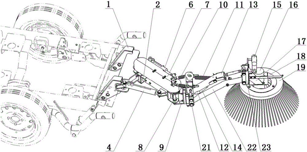
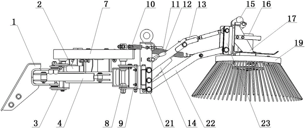
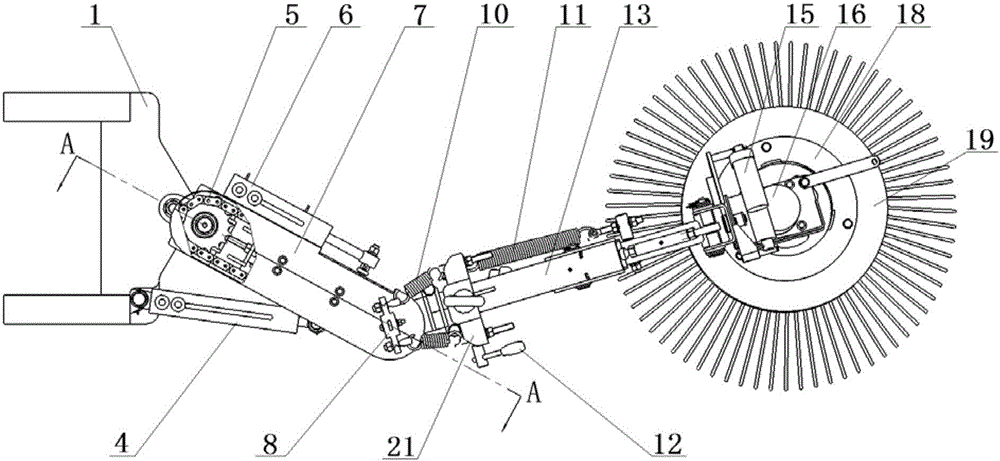
The invention relates to an additional sweeping device of a road sweeper and the road sweeper. The additional sweeping device of the road sweeper comprises an extension arm assembly, a front arm assembly, a sweeping assembly and a first driving part (4), wherein the front arm assembly is arranged between the extension arm assembly and the sweeping assembly, a first end of the extension arm assembly is detachably mounted on a chassis frame of the road sweeper and can horizontally swing under the driving of the first driving part (4), and accordingly, the front arm assembly drives the sweeping assembly to realize switching of a left side sweeping area and a right side sweeping area. The additional sweeping device can be controlled independently, the sweeping assembly can be flexibly controlled to swing leftwards and rightwards according to requirements of the sweeping road condition, and the position of the sweeping assembly is adjusted, so that controllability and accuracy of the sweeping position of the sweeping assembly are improved, and the stability of the additional sweeping device during working is improved; besides, the additional sweeping device can be independently mounted on the chassis frame of the road sweeper, and is convenient to mount, dismount and maintain.

Description

technical field [0001] The invention relates to the technical field of sanitation machinery, in particular to an additional sweeping device for a road sweeper and the road sweeper. Background technique [0002] Road sweeper is a kind of mechanical equipment with special chassis and power drive device, which is used to remove and collect ground or road surface rubbish. Road sweepers are not only suitable for the cleaning and maintenance of urban arterial roads, but also for cleaning work in squares, parks, schools or communities. Generally, the sweeping width of the road sweeper mainly depends on the sweeping width of the two main brushes. In order to meet the needs of driving transition or cleaning operations, the sweeping width of the two main brushes can only be slightly wider than the width of the entire vehicle. The width is greatly restricted. [0003] In order to increase the sweeping width of existing road sweepers, an additional sweeping device (or a third brush de...

Claims


Application Information

Patent Timeline
Patent Type & Authority Applications(China)
IPC IPC(8): E01H1/05
CPCE01H1/053
Inventor 王金东郭兵贾文彬焦中兴
Owner JIANGSU XCMG CONSTR MASCH RES INST LTD
Learn More