A support structure and method for an thermal insulation outer guard plate at an expansion joint

A technology for supporting structures and outer guard plates, applied in the direction of thermal insulation, building thermal insulation materials, building components, etc., can solve the problems of difficult construction, waste of steel, and lower thermal insulation performance of thermal insulation materials, so as to shorten the installation period, simplify installation and save energy. The effect of steel and artificial

Active Publication Date: 2018-08-10
POWERCHINA SEPCO1 ELECTRIC POWER CONSTR CO LTD +1
View PDF7 Cites 0 Cited by
  • Summary
  • Abstract
  • Description
  • Claims
  • Application Information

AI Technical Summary

Problems solved by technology

Since the expansion joints tend to expand axially and radially during the expansion process, although some outer guard plates at the expansion joints take into account the axial expansion and contraction of the expansion joints, the radial expansion and contraction of the expansion joints are often ignored. Contraction, due to the different expansion degrees of adjacent expansion joints, the movement of the outer guards is different. At this time, the outer guards of adjacent expansion joints will interact with each other, causing the outer guards at the expansion joints to be out of joint
After the outer shield is disconnected, it is easy to cause water vapor and rainwater to enter the insulation layer, which not only reduces the thermal insulation performance of the insulation material, but also affects the appearance of the insulation outer shield
[0003] In addition, because the support structure of the thermal insulation outer shield at the expansion joint is mostly made of large-area steel plates, it generally has disadvantages such as bulky materials, affecting expansion, wasting steel, and difficult construction.

Method used


Image

  • A support structure and method for an thermal insulation outer guard plate at an expansion joint
  • A support structure and method for an thermal insulation outer guard plate at an expansion joint
  • A support structure and method for an thermal insulation outer guard plate at an expansion joint

Examples


Embodiment Construction

[0036] The present invention will be further described below in conjunction with specific examples.

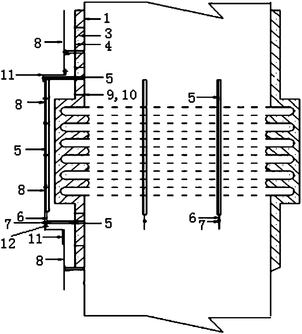
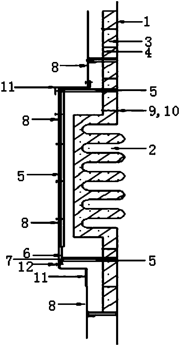
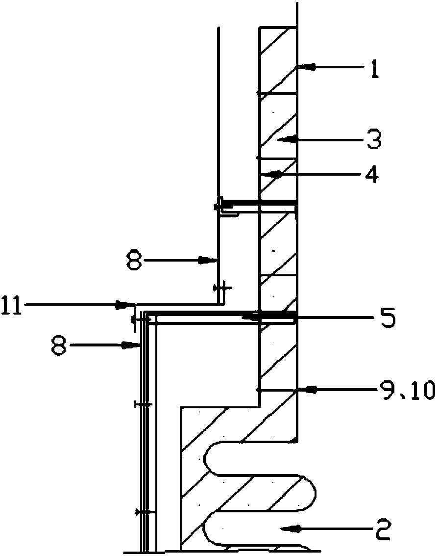
[0037] Such as Figure 1 to Figure 4 As shown, a construction plan for the support structure of the thermal insulation outer shield at the expansion joint, including several supports, the outer shield 8, the limit support 7 and the sliding end guide rod 6, one end of the support is fixed on the expansion On the housing at one end of section 2, the other end of the support member is fixedly connected with the sliding end guide rod 6;

[0038] The limit support 7 is fixed on the housing at the other end of the expansion joint 2, a guide hole is set on the limit support 7, and the free end of the sliding support 6 is inserted into the guide hole; the outer guard plate 8 is installed on the outer surface of the support plate.

[0039] The surface of the guide hole is smooth, and the outer surface of the sliding end guide rod 6 is smooth.

[0040] The length of the outer guard p...


PUM


Abstract

The invention discloses a supporting structure of a thermal-insulation outer protective board at an expansion joint and a method. The supporting structure comprises supporting parts, outer protective boards, limiting supports and sliding end guide rods, wherein one end of each supporting part is fixed on a casing at one end of the expansion joint, and the other end of each supporting part is fixedly connected with the corresponding sliding end guide rod; the limiting supports are fixed on the casing at the other end of the expansion joint, guide holes are formed in the limiting supports, and free ends of the sliding end guide rods are inserted into the guide holes; the outer protective boards are mounted on outer surfaces of the supporting parts. The supporting structure of the thermal-insulation outer protective board at the expansion joint comprises a fixing end and a sliding end, the fixing end plays supporting and fixing roles while the sliding end plays guiding and expansion allowance controlling roles, the thermal-insulation outer protective boards are mounted on the supporting structure and can have certain displacement along with the supporting structure, adjacent outer protective boards are connected through angle plates in a covering manner, disjoining of the outer protective boards is avoided, and vapor and rainwater are prevented from entering thermal-insulation layers.

Description

technical field [0001] The invention specifically relates to a support structure and method for an thermal insulation outer guard plate at an expansion joint. technical background [0002] The conventionally designed support structure of the thermal insulation outer shield at the expansion joint often adopts the method of installing a large area of ​​steel plate, and the expansion amount of the expansion outer shield support structure of the expansion joint is often considered too little. Since the expansion joints tend to expand axially and radially during the expansion process, although some outer guard plates at the expansion joints take into account the axial expansion and contraction of the expansion joints, the radial expansion and contraction of the expansion joints are often ignored. Contraction, due to the different expansion degrees of the adjacent expansion joints, the movement of the outer guards is different. At this time, the outer guards of the adjacent expans...

Claims


Application Information

Patent Timeline
Patent Type & Authority Patents(China)
IPC IPC(8): E04B1/66E04B1/76
CPCE04B1/66E04B1/76
Inventor 付深清马勃李世越
Owner POWERCHINA SEPCO1 ELECTRIC POWER CONSTR CO LTD
Why Eureka
Try Eureka