
Lifting lug for ceiling unit

A lifting ear and unit technology, applied in the direction of the ceiling, building components, buildings, etc., can solve the problems of falling equipment, loose bolts, insufficient strength, etc., and achieve the effect of saving space, low cost and small volume

Inactive Publication Date: 2017-01-11
ZIBO QIYU AIRCONDITION ENERGY RECOVERY EQUIP
View PDF0 Cites 0 Cited by
  • Summary
  • Abstract
  • Description
  • Claims
  • Application Information

AI Technical Summary

Problems solved by technology

[0004] Second, ordinary lifting lugs are generally welded or bolted to the surface of the hoisting equipment, resulting in insufficient strength and loose bolts, which will cause the equipment to fall

Method used


Image

  • Lifting lug for ceiling unit
  • Lifting lug for ceiling unit
  • Lifting lug for ceiling unit

Examples


Embodiment 1

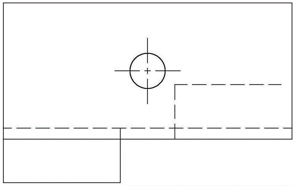
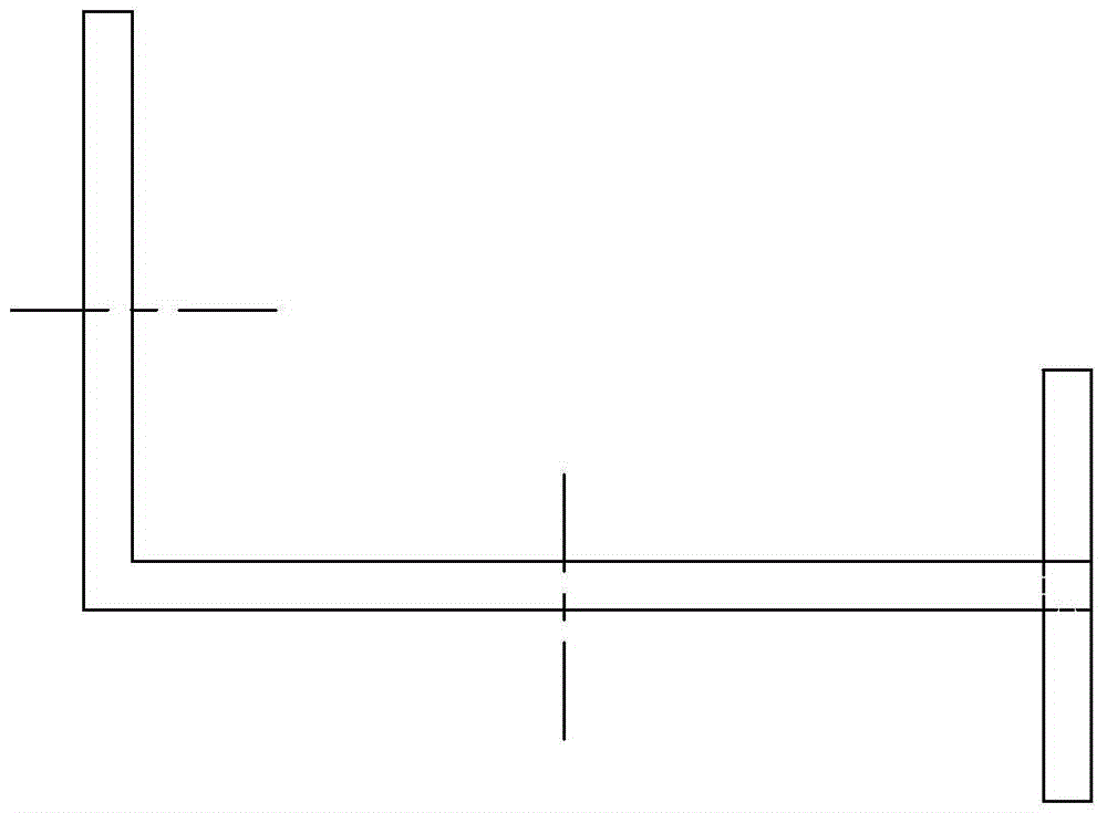
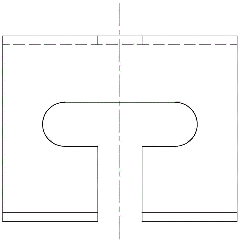
[0020] Embodiment 1: as figure 1 As shown, the hanging lug of the ceiling unit according to the present invention includes the lifting lug 1, the lifting lug 1 includes a horizontal part 2 and a vertical part 3, the horizontal part 2 and the vertical part 3 are perpendicular to each other, and the vertical part 3 is provided with a fixing hole 4. The horizontal part 2 is provided with a "U"-shaped through hole 5.

Embodiment 2

[0021] Embodiment 2: On the basis of the structure described in Embodiment 1, one end of the horizontal part 2 is provided with an upper reinforcement rib 6 and a lower reinforcement rib 7, and the upper reinforcement rib 6 and the lower reinforcement rib 7 are respectively located in the "U"-shaped through hole 5 on both sides of the opening.

Embodiment 3

[0022] Embodiment 3: On the basis of the structure described in Embodiment 2, the unopened end of the "U"-shaped through hole 5 communicates with an adjustment through hole 8 .


PUM


Abstract

The invention provides a lifting lug for a ceiling unit and belongs to the field of fixing devices. The lifting lug comprises a lifting lug body. The lifting lug body comprises a horizontal part and a vertical part; the horizontal part and the vertical part are perpendicular to each other; a fixing hole is formed in the vertical part; and a U-shaped through hole is formed in the horizontal part. The lifting lug for the ceiling unit is low in cost, small in occupied space and high in strength, and can ensure equipment safety when screws are loosened.

Description

technical field [0001] The invention provides a hanging lug of a ceiling unit, which belongs to the field of fixing devices. Background technique [0002] When installing the ceiling unit, it is all hoisted by lifting lugs or unit suspenders, so that the screws hang it on the roof. The current technical defects are: [0003] First, the cost of hoisting is relatively high, and it takes up a lot of space, which makes the cost of hoisting and the amount of space occupied very high; [0004] Second, ordinary lifting lugs are generally welded or bolted to the surface of the hoisting equipment, resulting in insufficient strength and loose bolts, which will cause the equipment to fall. Contents of the invention [0005] The purpose of the present invention is to provide a hanging lug of a ceiling unit, which has low cost, low space occupation, high strength, and can ensure the safety of the equipment when the screws are loose. [0006] The lifting lug of the ceiling unit accord...

Claims


Application Information

Patent Timeline
Patent Type & Authority Applications(China)
IPC IPC(8): E04B9/18E04B9/20
Inventor 宋波刘甲李翔杨洪涛
Owner ZIBO QIYU AIRCONDITION ENERGY RECOVERY EQUIP
Learn More