Method for controlling diluent or lean mixed gas burning and ignition through high-flammability fuel micro ignition

A lean-burn, fuel technology, applied in fuel injection control, electrical control, engine control and other directions, can solve the problems of high pressure rise rate of gasoline engine under heavy load, lack of ignition control method for gasoline compression ignition combustion, high pressure, etc. Effects of improved economy, improved fuel economy, and reduced NOx emissions

Inactive Publication Date: 2017-01-11
TIANJIN UNIV
View PDF5 Cites 19 Cited by
  • Summary
  • Abstract
  • Description
  • Claims
  • Application Information

AI Technical Summary

Problems solved by technology

The ignition of gasoline compression ignition combustion depends on the temperature history of the premixed charge in the cylinder during the compression process. The ignition is essentially determined by the chemical reaction kinetics and the flow mixing process in the cylinder, but the chemical reaction kinetics and the flow mixing process in the cylinder Both are difficult to directly and accurately control, so gasoline compression ignition combustion lacks a direct ignition control method to precisely control the ignition time
Secondly, gasoline compression ignition combustion is very sensitive to ambient temperature, so it is difficult to stably ignite when the engine is in a cold environment, such as cold start
Finally, the gasoline engine has a problem of high pressure rise rate under heavy load
Due to the lack of effective control means for ignition timing and combustion process, gasoline compression ignition combustion is easy to cause high pressure rise rate due to high heat release rate under heavy load
High pressure rise rate can cause engine damage

Method used


Image

  • Method for controlling diluent or lean mixed gas burning and ignition through high-flammability fuel micro ignition
  • Method for controlling diluent or lean mixed gas burning and ignition through high-flammability fuel micro ignition
  • Method for controlling diluent or lean mixed gas burning and ignition through high-flammability fuel micro ignition

Examples


Embodiment Construction

[0035] The technical solution of the present invention will be further described in detail below in conjunction with the accompanying drawings and specific embodiments, and the described specific embodiments are only for explaining the present invention, and are not intended to limit the present invention.

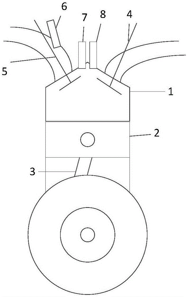
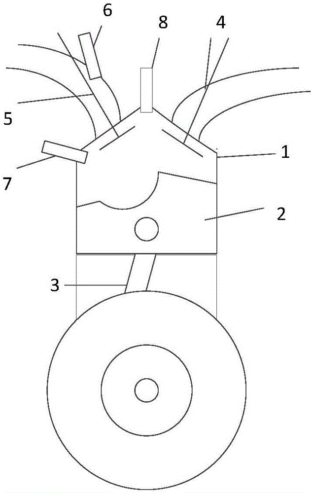
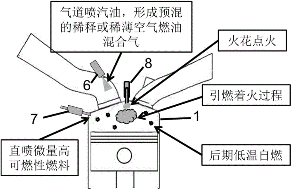
[0036] In the present invention, the energy released during the micro-ignition process of early injection of highly flammable fuel is distributed as a small heat source group in a spatial area, and the auxiliary premixed diluted mixture produces multiple spontaneous ignition points, and then multi-point spontaneous combustion or rapid ignition occurs. combustion. The micro-ignition process of late injection of highly flammable fuel is to strengthen the flame propagation process through the self-ignition of highly flammable fuel to generate a large number of concentrated micro-ignition sources, so that the rest of the diluted air-fuel mixture or lean air-fuel mixture can obt...


PUM


Abstract

The invention discloses a method for controlling diluent or lean mixed gas burning and ignition through high-flammability fuel micro ignition. The method comprises the steps that gasoline is ignited through spontaneous burning of a small amount of layered high-flammability fuel, and stable flame propagation is formed; the temperature inside a cylinder is increased through energy released by flame propagation and piston upward compression, meanwhile, multiple spontaneous burning points are formed in unburnt diluent or lean mixed gas under the assistance of a small amount of pilot injection high-flammability fuel, and then stable and rapid burning or multi-point spontaneous burning is formed. When an engine encounters knock or the largest explosion pressure exceeds limits, the burning process can be converted into rapid flame propagation type burning by introducing cooled burnt waste gas or excess air. When the heat state in the cylinder is not enough to form stable flame propagation or spontaneous burning heat release, the heat state in the cylinder is improved by introducing internal residual waste gas. The control problem in the ignition and burning process of premixed diluent or lean mixed gas can be solved.

Description

technical field [0001] The invention relates to an engine combustion control technology. Background technique [0002] Gasoline compression ignition (GCI) has become a promising new engine combustion technology because of its potential to improve fuel economy and engine exhaust emissions. In the development history of gasoline compression ignition technology, due to different application platforms and control strategies, it is also called premixed charge compression ignition technology, homogeneous charge compression ignition technology, controlled spontaneous combustion technology and partial premixed charge ignition technology. Compression ignition technology, etc. Although the above several technologies are different in implementation, their technical cores belong to the category of gasoline compression ignition ignition combustion. One of the common characteristics of gasoline compression ignition combustion technology is that the dilute or lean air-fuel mixture is spo...

Claims


Application Information

Patent Timeline
Patent Type & Authority Applications(China)
IPC IPC(8): F02D41/30F02D41/00F02M26/05F02M26/06F02D37/02F02D19/06F02D21/08
CPCF02D19/06F02D21/08F02D37/02F02D41/0025F02D41/005F02D41/3094Y02T10/30
Inventor 谢辉陈韬李洪涛赵华
Owner TIANJIN UNIV
Why Eureka
Try Eureka