Oil stop device, rotor assembly, compressor and air conditioning equipment

A technology of rotors and components, applied in the field of compressors, can solve problems such as fixed flow area and inability to adapt to different operating conditions of compressors

Active Publication Date: 2017-01-11
GREE ELECTRIC APPLIANCES INC +1
View PDF11 Cites 0 Cited by
  • Summary
  • Abstract
  • Description
  • Claims
  • Application Information

AI Technical Summary

Problems solved by technology

[0004] The embodiment of the present invention provides an oil retaining device, a rotor assembly, a compressor and an air conditioner to solve the problem in the prior art that the flow area is fixed and cannot adapt to different operating conditions of the compressor

Method used


Image

  • Oil stop device, rotor assembly, compressor and air conditioning equipment
  • Oil stop device, rotor assembly, compressor and air conditioning equipment
  • Oil stop device, rotor assembly, compressor and air conditioning equipment

Examples


Embodiment Construction

[0035] The present invention will be further described in detail below with reference to the drawings and specific embodiments, but it is not intended to limit the present invention.

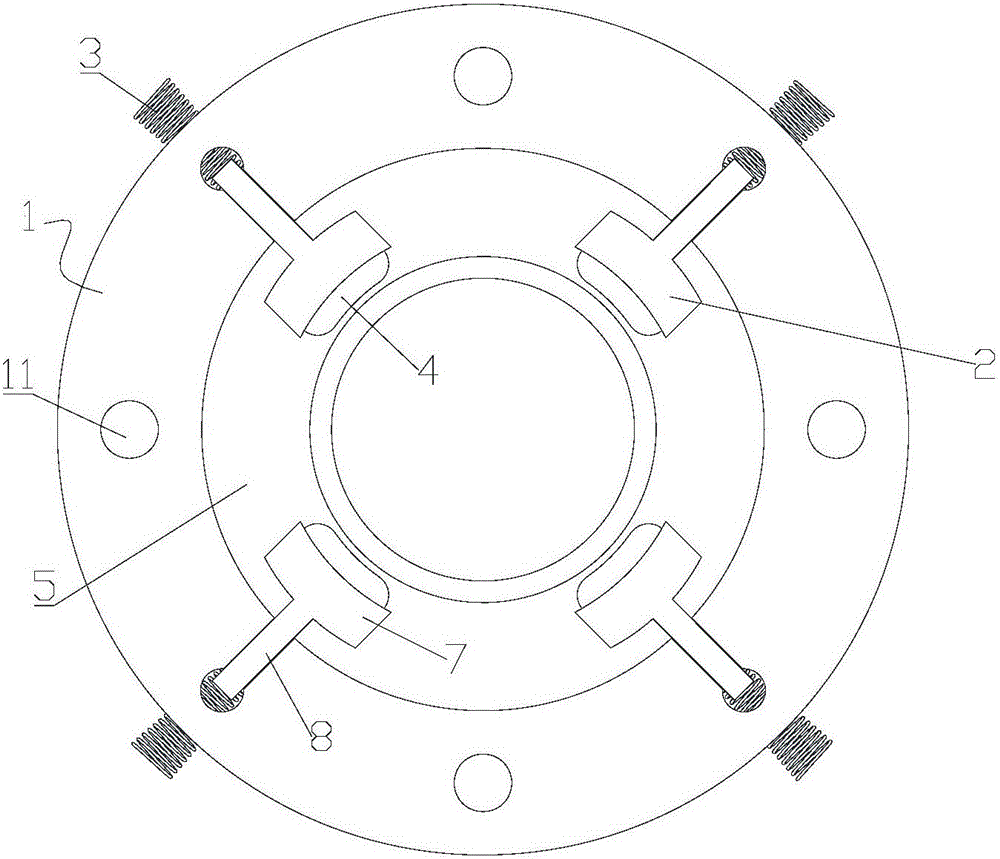
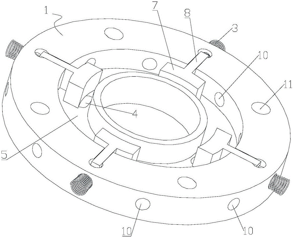
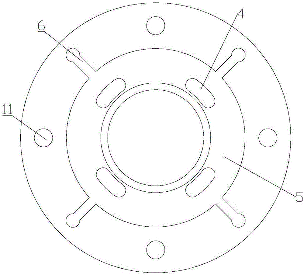
[0036] Please refer to Figure 1 to Figure 8 , The oil blocking device of the present invention can be used in a rotor assembly, which includes a body 1, a slider 2, and an elastic element 3. For example, the body 1 has a cylindrical pie-shaped structure, and the elastic element 3 can provide elastic force to balance the centrifugal force generated by the slider 2 when the rotor assembly rotates.

[0037] Among them, the slider 2 is movably arranged on the body 1 and can move along the radial direction of the body 1. The body 1 has one or more air inlets 4 which are arranged on the movement path of the slider 2. The elastic element 3 is installed on the body 1. When the oil blocking device in the present invention is in a static state, the elastic element 3 provides a force to the slider 2 to drive...


PUM


Abstract

The invention discloses an oil stop device, a rotor assembly, a compressor and air conditioning equipment. The oil stop device comprises a body, sliding blocks and elastic elements. The sliding blocks are movably connected with the body; the body is provided with air inlets which are located in the moving paths of the sliding blocks; and the elastic elements drive the sliding blocks to block the air inlets when the oil stop device is in the stationary state. By means of the oil stop device, the rotor circulation area can adapt to the operation conditions of the compressor, specifically, when the refrigerating amount is small and the large circulation area is not needed, the circulation area of the rotor assembly is reduced, and accordingly, loss of refrigeration oil is reduced; and when the refrigerating amount is large, the circulation area is increased, and the refrigerant circulation rate is guaranteed.

Description

Technical field [0001] The present invention relates to the technical field of compressors, and in particular to an oil blocking device, a rotor assembly, a compressor and an air conditioner. Background technique [0002] In the prior art, the rotor assembly of the inverter compressor is provided with a circulation structure. The circulation structure usually has a circulation hole on the iron core and a corresponding circulation hole on the baffle to increase the circulation area of ​​refrigerant and refrigerating oil. [0003] However, under this structure, the gaseous refrigerant containing a certain amount of refrigerating oil will flow out directly through the circulation hole and enter the air conditioning system, reducing the refrigerating oil of the compressor. In addition, because the flow area is fixed, it cannot adapt to the different working conditions of the compressor during operation, and the flow area cannot be reduced in time without the need for a large flow area ...

Claims


Application Information

Patent Timeline
IPC IPC(8): F04C29/00
CPCF04C29/00
Inventor 刘才刘锋朱晓光
Owner GREE ELECTRIC APPLIANCES INC
Why Eureka
Try Eureka