Magnetic control valve used for industrial production and having mixing function

An electromagnetic control valve and function technology, applied in the field of mechanical seals, can solve the problems of increased material cost, complex installation structure, inability to block three-way or four-way valves, etc., and achieves reasonable structural design, good blocking effect, and convenient operation. Effect

Active Publication Date: 2017-01-11
中山市城润电子科技有限公司
View PDF6 Cites 4 Cited by
  • Summary
  • Abstract
  • Description
  • Claims
  • Application Information

AI Technical Summary

Problems solved by technology

[0002] At present, in the production and manufacturing process of industrial products, when it comes to the addition of liquid raw materials, it is inseparable from the pipeline, the connection between the pipelines and the valve on the pipeline to control and adjust the flow, especially the common "T"-shaped tee Or "ten"-shaped four-way, which is convenient for the connection between multiple pipes. After the connection, it needs to be used in conjunction with multiple valves. Generally, at least 2-4 valves are required, which increases the cost of materials and complicates the installation structure. When the raw material liquid is transported, it is necessary to manually open a valve, which has low flexibility and is laborious to adjust. After the raw material liquid is transported, it needs to cooperate with the corresponding mixing and stirring device to increase the adequacy of mixing between the raw material liquids, which is extremely inconvenient to operate. The three-way or four-way valve cannot be blocked according to the actual use requirements to realize the adjustment of the conveying structure, the sealing performance is poor, and the stability is low

Method used


Image

  • Magnetic control valve used for industrial production and having mixing function
  • Magnetic control valve used for industrial production and having mixing function
  • Magnetic control valve used for industrial production and having mixing function

Examples


Embodiment Construction

[0015] The following will clearly and completely describe the technical solutions in the embodiments of the present invention with reference to the accompanying drawings in the embodiments of the present invention. Obviously, the described embodiments are only some, not all, embodiments of the present invention. Based on the embodiments of the present invention, all other embodiments obtained by persons of ordinary skill in the art without making creative efforts belong to the protection scope of the present invention.

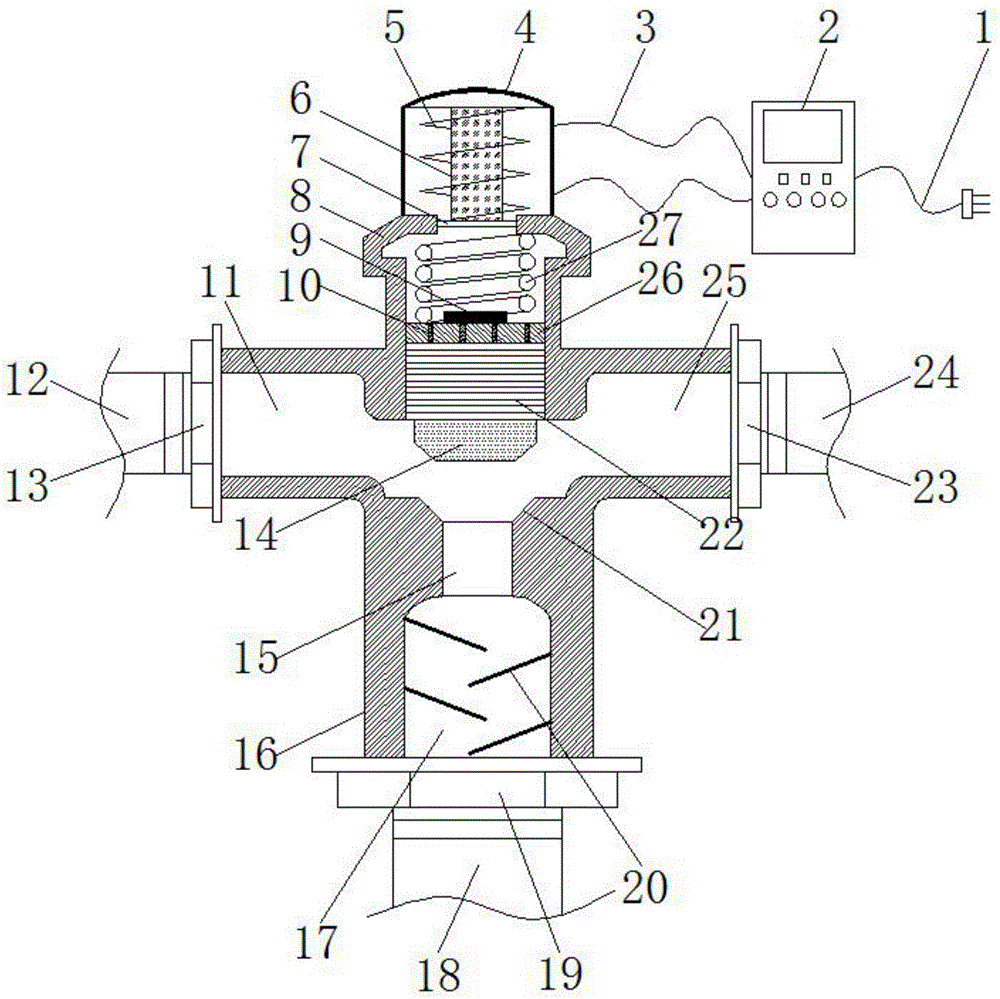
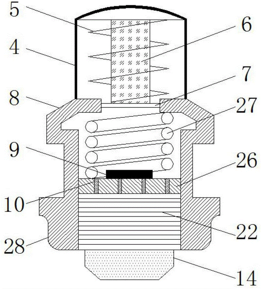
[0016] see Figure 1~3 , in an embodiment of the present invention, an electromagnetic control valve with a mixing function for industrial production, including a valve core body 14, a valve body 16 and a pressure spring 27, a valve seat 28 is provided at the upper end of the valve body 16, and the inside of the valve seat 28 A spool body 14 is slidingly arranged, and the outer surface of the spool body 14 is provided with a number of O-rings 22, the O-rings 2...


PUM


Abstract

The invention discloses a magnetic control valve used for industrial production and having a mixing function. The magnetic control valve comprises a valve core body, a valve body and a pressure spring, wherein a valve seat is arranged at the upper end of the valve body, the valve core body is arranged in the valve seat in a sliding mode, a valve body guide rod is arranged inside the valve core body, the upper end of the valve body guide rod extends out of a valve body rear cover, the valve body rear cover is arranged at the upper end of the valve core body, the pressure spring is arranged above the valve body guide rod, the bottom of the pressure spring is fixed to the valve body rear cover, the top of the pressure spring is fixed in a spring seat, the spring seat is arranged at the upper end of the valve seat, the upper end of the spring seat is connected with a sealing top cover, a partition plate is arranged at the connecting position of the sealing top cover and the spring seat, and an irony core is vertically fixed in the sealing top cover above the partition plate and is sleeved with a coil. The magnetic control valve used for industrial production and having the mixing function has a good plugging effect, facilitates control of liquid output flow, saves time and labor and is good in stability.

Description

technical field [0001] The invention relates to the field of mechanical seals, in particular to an electromagnetic control valve with mixing function for industrial production. Background technique [0002] At present, in the production and manufacturing process of industrial products, when it comes to the addition of liquid raw materials, it is inseparable from the pipeline, the connection between the pipelines and the valve on the pipeline to control and adjust the flow, especially the common "T"-shaped tee Or "ten"-shaped four-way, which is convenient for the connection between multiple pipes. After the connection, it needs to be used in conjunction with multiple valves. Generally, at least 2-4 valves are required, which increases the cost of materials and complicates the installation structure. When the raw material liquid is transported, it is necessary to manually open a valve, which has low flexibility and is laborious to adjust. After the raw material liquid is trans...

Claims


Application Information

Patent Timeline
Patent Type & Authority Applications(China)
IPC IPC(8): F16K11/04F16K31/06
CPCF16K1/32F16K11/04F16K31/0624
Inventor 丁艺敏
Owner 中山市城润电子科技有限公司
Why Eureka
Try Eureka