
Stove burner

A technology for burners and stoves, which is applied in the direction of burners, gas fuel burners, combustion methods, etc. It can solve the problems of spark plug damage, insufficient restriction of ignition flame holes, and uneconomical problems, and achieve the effect of improving fire transmission

Active Publication Date: 2017-01-11
RINNAI CORP
View PDF7 Cites 2 Cited by
  • Summary
  • Abstract
  • Description
  • Claims
  • Application Information

AI Technical Summary

Problems solved by technology

In this case, as in the prior art, the mixture gas is restricted to an appropriate amount of gas through the ignition hole. Once the groove of the ignition hole is opened, the restriction of the mixture gas by the ignition hole becomes less. Sufficient, the flame for ignition is formed larger
Therefore, excessive burning of the spark plug occurs and damage to the spark plug occurs
Moreover, if the supply amount of the mixed gas used for ignition is too large, the consumption of gas will increase, which is not economical.

Method used


Image

  • Stove burner
  • Stove burner
  • Stove burner

Examples


Embodiment Construction

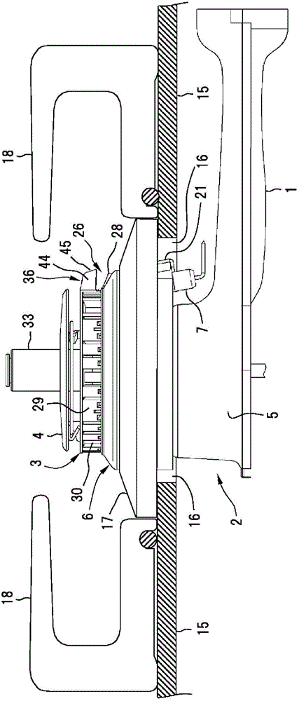
[0054] An embodiment of the present invention will be described with reference to the drawings. Such as figure 1 As shown, the burner for a stove of this embodiment includes a mixing tube 1 , a burner body 2 , a burner head 3 and a burner cover 4 .

[0055] A mixture of gas and primary air is generated in the mixing tube 1 by introducing gas and primary air sprayed from a gas nozzle not shown.

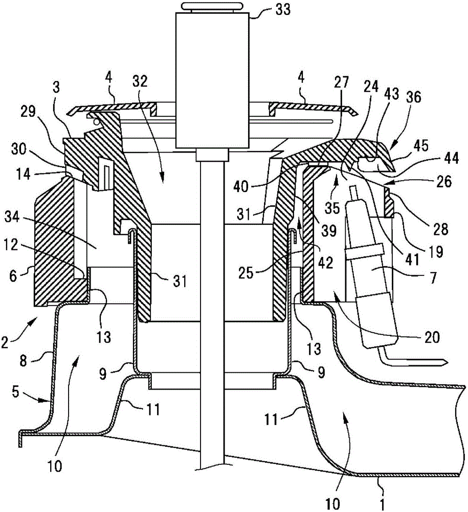
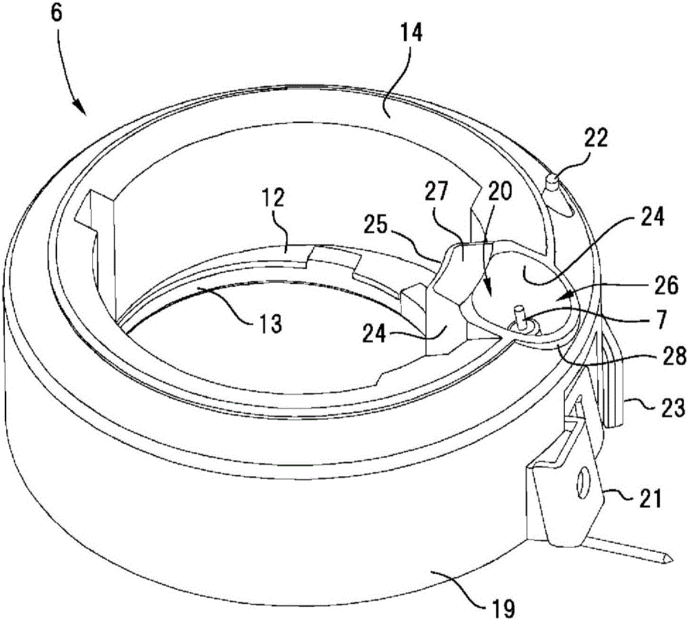
[0056] Such as figure 2 As shown, a burner body 2 is connected to the downstream end of the mixing tube 1 . The burner body 2 includes a base portion 5 formed of a metal plate and a spacer 6 formed by die casting. A spark plug 7 is arranged inside the spacer 6 .

[0057] The base portion 5 of the burner body 2 includes an outer cylinder 8 and an inner cylinder 9 provided inside the outer cylinder 8 . An annular space formed between the outer cylinder 8 and the inner cylinder 9 constitutes a mixed gas passage 10 communicating with the mixing tube 1 .

[0058] Such as figure 2 As ...


PUM


Abstract

The invention provides a stove burner. A spark plug storage part for storing a spark plug is arranged on a main burner body and provided with a pair of first side walls and a first rear wall; an ignition part covering above the spark plug is arranged at a burner head part and provided with a pair of second side walls abutting against the outer side surfaces of the two first side walls of the spark plug storage part as well as a second rear wall opposite to the inner side surface of the first rear wall; the lower surface of the ignition part abuts against the upper end surface of the first rear wall, and ignition holes are formed; and an ignition gas guide channel used for supplying a gas mixture in a distribution chamber to the ignition holes is formed between the first rear wall and the second rear wall. When the stove burner is used, the best ignition gas mixture supply state can be maintained without being affected by a gap even when the gap is generated between the burner head part and the main burner body.

Description

technical field [0001] The present invention relates to a stove burner used in a gas stove. Background technique [0002] Generally speaking, a stove burner has: a mixing tube for supplying the mixture of gas and primary air; a burner body connected to the mixing tube and forming a distribution chamber inside; An annular burner head forming a main flame hole (referred to in this specification as a flame hole for forming a cooking heating flame, the flame hole is composed of a plurality of flame holes of different shapes and sizes) and an ignition hole; and , the spark plug that generates spark discharge near the ignition hole. [0003] Among such burners for stoves, there is known a burner in which a spark plug is formed and housed in a part of the outer peripheral portion of a burner body (see Patent Document 1 below). By housing the spark plug in a part of the burner body, the upper part of the spark plug is covered by a part of the burner head. Furthermore, an ignition...

Claims


Application Information

Patent Timeline
Patent Type & Authority Applications(China)
IPC IPC(8): F23D14/02
Inventor 佐藤裕康武田和也
Owner RINNAI CORP
Learn More