A temperature compensation method for distributed Raman temperature sensor

A temperature sensor and temperature compensation technology, applied in thermometers, thermometer testing/calibration, thermometers with physical/chemical changes, etc. and other problems to achieve the effect of improving the environmental adaptation range, ensuring the accuracy of temperature measurement, and ensuring temperature adaptability

Active Publication Date: 2019-03-22
CHINA ELECTRIC POWER RES INST +3
View PDF7 Cites 0 Cited by
  • Summary
  • Abstract
  • Description
  • Claims
  • Application Information

AI Technical Summary

Problems solved by technology

[0005] 2. Anti-Stokes Raman self-demodulation or Rayleigh demodulation anti-Stokes Raman, this demodulation method is relatively difficult to calibrate the temperature, and engineering application is inconvenient, so it is rarely used in the industry
[0006] 3. Stokes Raman self-demodulation, relatively low temperature sensitivity, only theoretical significance and no application value
Since the Stokes Raman and anti-Stokes Raman in the distributed optical fiber Raman temperature sensor will be mixed with some optical noise, the measured temperature value of the sensing fiber will be different from the actual temperature value when the temperature of the calibration fiber changes. There will be deviations

Method used


Image

  • A temperature compensation method for distributed Raman temperature sensor
  • A temperature compensation method for distributed Raman temperature sensor
  • A temperature compensation method for distributed Raman temperature sensor

Examples


Embodiment 1

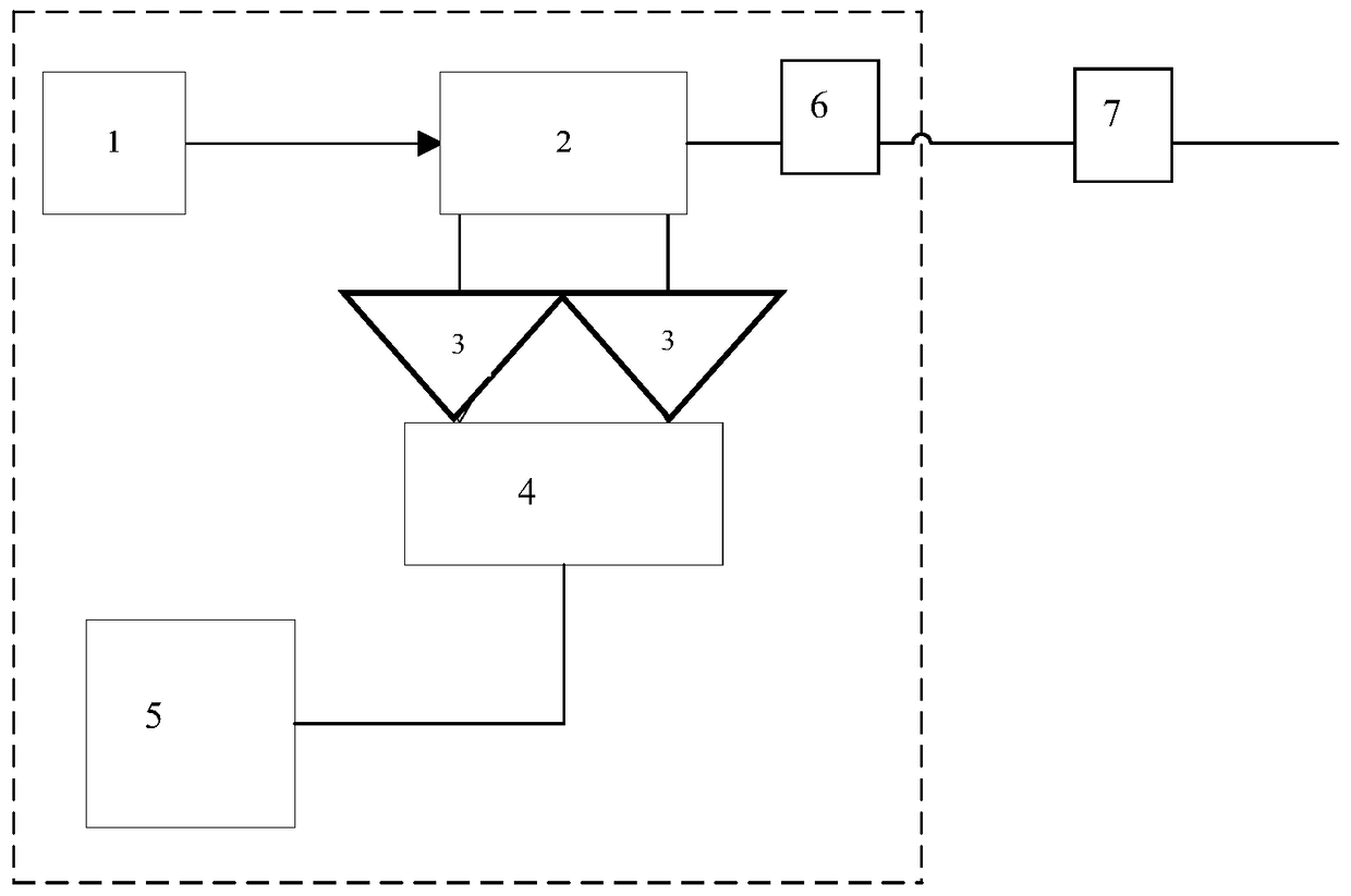
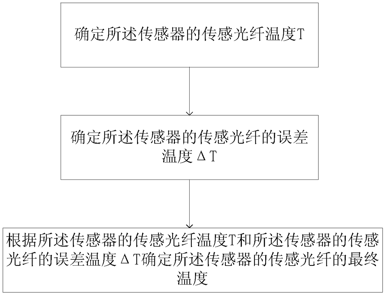
[0036] The invention of this example provides a temperature compensation method for a distributed Raman temperature sensor, such as figure 2 shown, including:

[0037] Determine the sensing fiber temperature T of the sensor;

[0038] determining the error temperature ΔT of the sensing fiber of the sensor;

[0039] The final temperature of the sensing fiber of the sensor is determined according to the temperature T of the sensing fiber of the sensor and the error temperature ΔT of the sensing fiber of the sensor.

[0040] The distributed optical fiber Raman temperature sensor is at a constant temperature, and the temperature of the calibration optical fiber is recorded as T 0a , the total length of the sensing fiber is denoted as L a , performing temperature calibration on the sensor under the temperature condition, and saving the parameters of the sensor.

[0041] Replace the ambient temperature of the distributed optical fiber Raman temperature sensor and keep the parame...


PUM


Abstract

The present invention relates to a temperature compensation method of a distributed Raman temperature sensor, comprising: determining the sensing fiber temperature T of the sensor; determining the error temperature ΔT of the sensing fiber of the sensor; according to the sensing fiber temperature of the sensor T and the error temperature ΔT of the sensing fiber of the sensor determine the final temperature of the sensing fiber of the sensor. The technical solution of the present invention overcomes the defect of the temperature change of the calibration optical fiber caused by the change of the ambient temperature of the temperature measurement host, and solves the problem that the temperature measurement accuracy of the sensor decreases and the temperature curve after demodulation is deformed. The problem.

Description

Technical field: [0001] The invention relates to the technical field of distributed optical fiber sensors, and more particularly relates to a temperature compensation method of a distributed Raman temperature sensor. Background technique: [0002] The distributed optical fiber temperature sensor system developed in recent years is used as a temperature-sensitive fire detector for linear fire monitoring temperature-sensing optical fibers. It can predict temperature changes online in real time, and can set alarm temperatures in a large temperature range. The optical fiber itself is not charged. It is an intrinsically safe linear temperature-sensitive fire detector that detects the temperature by the change of the light intensity transmitted in the optical fiber or the change of the spectral position. It can also be called the fiber optic laser temperature radar. Engineering and other security testing has been successfully applied. [0003] In some occasions in engineering app...

Claims


Application Information

Patent Timeline
Patent Type & Authority Patents(China)
IPC IPC(8): G01K11/32G01K15/00G01K11/324
Inventor 雷煜卿陈希汪洋张睿汭史振国张永臣刘伟
Owner CHINA ELECTRIC POWER RES INST
Why Eureka
Try Eureka