Massive accumulation body boundary resistance experiment determination device and experimental method

A measuring device and stacking body technology, applied in the direction of measuring devices, surface/boundary effects, force/torque/work measuring instruments, etc., can solve the problem of prolonging the time for rescuers to arrive at the area where rescuers are waiting, and roadway instability and collapse. , Rescue obstruction and other issues

Inactive Publication Date: 2017-01-11
HEILONGJIANG UNIVERSITY OF SCIENCE AND TECHNOLOGY
View PDF5 Cites 1 Cited by
  • Summary
  • Abstract
  • Description
  • Claims
  • Application Information

AI Technical Summary

Problems solved by technology

[0004] After the disaster, the roadway became unstable and collapsed, resulting in the blockage of the rescue channel, which led to the obstruction of rescue and prolonged the time for rescuers to reach the area where the people waiting for rescue are stationed. key

Method used


Image

  • Massive accumulation body boundary resistance experiment determination device and experimental method
  • Massive accumulation body boundary resistance experiment determination device and experimental method
  • Massive accumulation body boundary resistance experiment determination device and experimental method

Examples


Embodiment 1

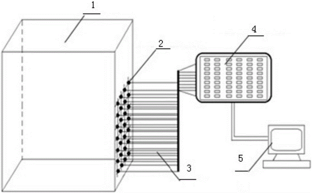
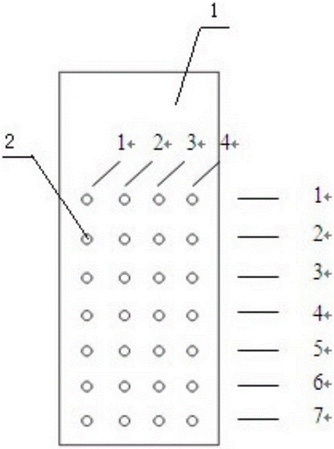
[0048] An experimental measuring device for boundary resistance of massive accumulations, which consists of: an experimental box 1, a pressure sensor 2, and a data line 3. A pressure sensor 2 is arranged on the side of the experimental box 1, and the pressure sensor 2 is arranged vertically 7 rows, 4 in each row, each of the pressure sensors 2 is connected to the data acquisition instrument 4 through the data line 3, and the data acquisition instrument 4 is connected to the computer 5 through the data line 3.

[0049] Pressure sensor model: KAP10 series IP65

[0050] Data acquisition instrument model: UT7160 static acquisition instrument

Embodiment 2

[0052] In the device for measuring the boundary resistance of massive accumulation bodies described in Example 1, the left side, right side and back side of the experimental box 1 are all wooden boards, and the top surface, bottom surface and front side of the experimental box 1 are all wooden boards. For the plexiglass plate.

Embodiment 3

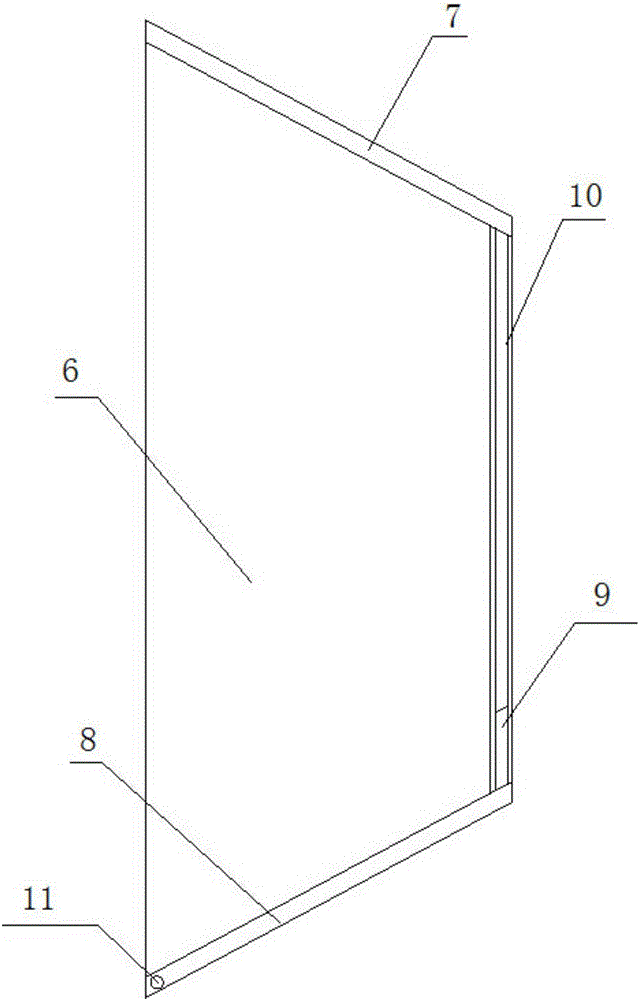
[0054] In the experimental measuring device for the boundary resistance of massive accumulation bodies described in embodiment 1 or 2, the top of the experimental box 1 is provided with a trough-shaped block dispersing inlet with an adjustable lower outlet width, and the trough-shaped block dispersing inlet is The two sides are respectively an isosceles trapezoidal glass plate I6 and an isosceles trapezoidal glass plate II. 7) It is connected with the plexiglass plate II8, the width of the upper entrance of the dispersed inlet of the groove-shaped block is greater than the width of the lower outlet, the plexiglass plate Ⅱ8 is an adjustable side, and the plexiglass plate Ⅱ8 The bottom end is provided with a slide bar 9, and the slide bar 9 slides in the chute 10, and the chute 10 is respectively arranged at the lower outlet ends of the isosceles trapezoidal glass plate I6 and the isosceles trapezoidal glass plate II. The top of the plexiglass plate II8 is respectively connected...


PUM

PropertyMeasurementUnit
particle diameteraaaaaaaaaa

Abstract

The invention relates to a massive accumulation body boundary resistance experiment determination device and an experimental method. An after-calamity roadway is unstable and collapsed to cause the blockage of a rescue path, so that rescue is blocked, the time of rescue workers for arriving a resident area of rescuable personnel is delayed, and at the moment, how to safely and quickly pass becomes a key of realizing safe, quick and effective rescue after calamity. Pressure sensors are arranged on the side face of an experiment box, and are arranged in seven columns longitudinally and four pieces in each row; each pressure sensor is connected with a data acquisition instrument through a data cable; the data acquisition instrument is connected with a computer through the data cables. The massive accumulation body boundary resistance experiment determination device and the experimental method provided by the invention are applied in experiments of accumulation body boundary passive resistance and horizontal force between massives.

Description

[0001] Technical field: [0002] The invention relates to an experimental measuring device and a testing method for the boundary resistance of massive accumulation bodies. [0003] Background technique: [0004] After the disaster, the roadway became unstable and collapsed, resulting in the blockage of the rescue channel, which led to the obstruction of rescue and prolonged the time for rescuers to reach the area where the people waiting for rescue are stationed. key. [0005] Invention content: [0006] The object of the present invention is to provide an experimental measuring device and test method for the boundary resistance of massive piles, provide the judging conditions for whether the caving piles can fill the space, and deduce the height and boundary level of the caving piles The calculation formula of the resistance force and the lateral and longitudinal force at any point in the accumulation body gives the distribution curve of the vertical and horizontal force bet...

Claims


Application Information

Patent Timeline
Patent Type & Authority Applications(China)
IPC IPC(8): G01N13/00G01L5/00
CPCG01N13/00G01L5/00
Inventor 张国华陈刚金珠鹏秦涛兰永伟
Owner HEILONGJIANG UNIVERSITY OF SCIENCE AND TECHNOLOGY
Why Eureka
Try Eureka