Longitudinal wave normal probe full-beam-path non-blind-area flaw detecting method

A longitudinal wave straight probe, no blind zone technology, used in the analysis of solids using sonic/ultrasonic/infrasonic waves, material analysis using sonic/ultrasonic/infrasonic waves, measurement devices, etc. problem, to achieve the effect of accurate defect characterization

Active Publication Date: 2017-01-11
TEWARE
View PDF6 Cites 12 Cited by
  • Summary
  • Abstract
  • Description
  • Claims
  • Application Information

AI Technical Summary

Problems solved by technology

[0010] Problem 1. There is a detection blind zone. The blind zone is the width occupied by the initial pulse (transmission pulse) of the oscilloscope screen. This width is determined by the chip size, frequency and flaw detection sensitivity of the probe. If the initial pulse width is 10 mm, then the workpiece surface 10 The reflected wave of the defect within the millimeter coincides with the initial pulse, so the defect cannot be distinguished;
[0011] Question 2. Near the wave source, a series of sound pressure maximum and minimum values ​​appear due to wave interference. This region is called the near-field region. When ultrasonic testing is performed in the near-field region, it is at the sound pressure extreme The echo of a large defect at a small value may be low, while the echo of a small defect at a maximum value of sound pressure may be high, which is likely to cause misjudgment and missed detection, so it should be avoided as much as possible in the near field area. Defect quantification; based on the formula near-field area N=D2 / 4λ, if there is a probe with a wafer diameter of 20 mm and a frequency of 5 MHz, the near-field area of ​​the probe is 84.7 mm. If a defect is found in the near-field area, it can only be detected manually Compare the test blocks to determine the defect equivalent, or calculate through the AVG curve;
[0012] Question 3. Each method only uses one sound wave for flaw detection. To find defects, only the distance between the defect surface and the detection surface and the equivalent size of the defect surface can be determined. If the three-dimensional size of the defect is to be detected, flaw detection must be carried out on several other surfaces , and at the same time, whether other surfaces can be inspected is not convenient for flaw detection, and even if flaw detection is possible, it is time-consuming and laborious, and the flaw detection efficiency is not high;
[0013] Question 4. The sensitivity of each method is adjusted according to the plane equivalent, and the defects found are calculated according to the plane defect equivalent, which itself is very different from the actual internal defects of the workpiece, thus causing error problems;
[0014] Question 5. The formulas for the equivalent calculation of each method are established when the sound path is beyond 3N, and within 3N, it is also necessary to rely on test blocks for comparison, or to calculate through the AVG curve;
[0015] Question 6. There is only one surface defect reflection wave, the qualitative can only be a reference, and there is a problem of low accuracy

Method used


Image

  • Longitudinal wave normal probe full-beam-path non-blind-area flaw detecting method
  • Longitudinal wave normal probe full-beam-path non-blind-area flaw detecting method
  • Longitudinal wave normal probe full-beam-path non-blind-area flaw detecting method

Examples


Embodiment Construction

[0094] In order to make the purpose, technical solutions and advantages of the present invention clearer, the technical solutions of the present invention will be clearly and completely described below in conjunction with the accompanying drawings in the embodiments of the present invention. Obviously, the described embodiments are part of the implementation of the present invention. example, not all examples. Based on the embodiments of the present invention, all other embodiments obtained by persons of ordinary skill in the art without making creative efforts belong to the protection scope of the present invention.

[0095] At first the corresponding design principle of the present invention is briefly described:

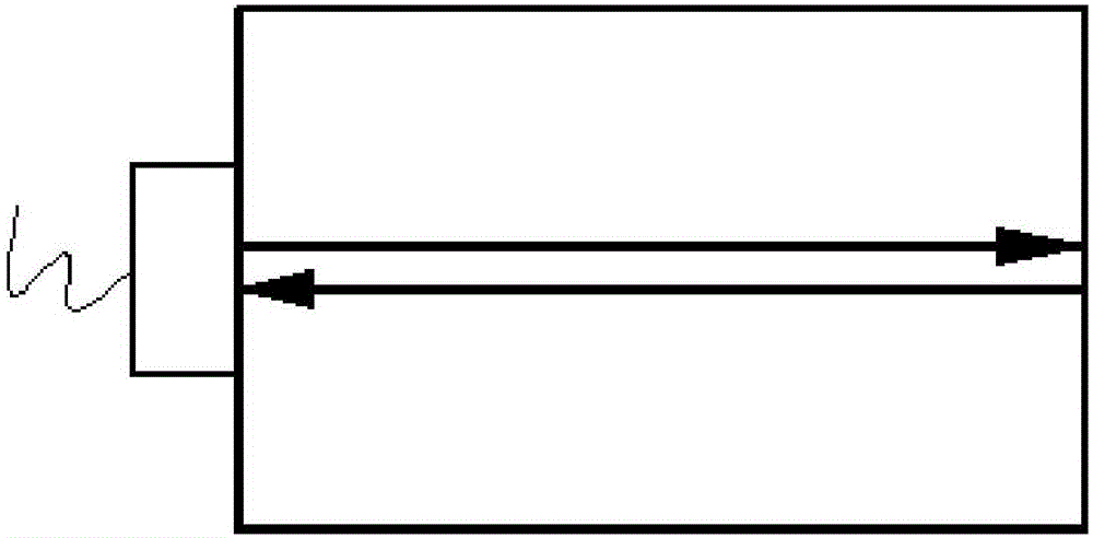
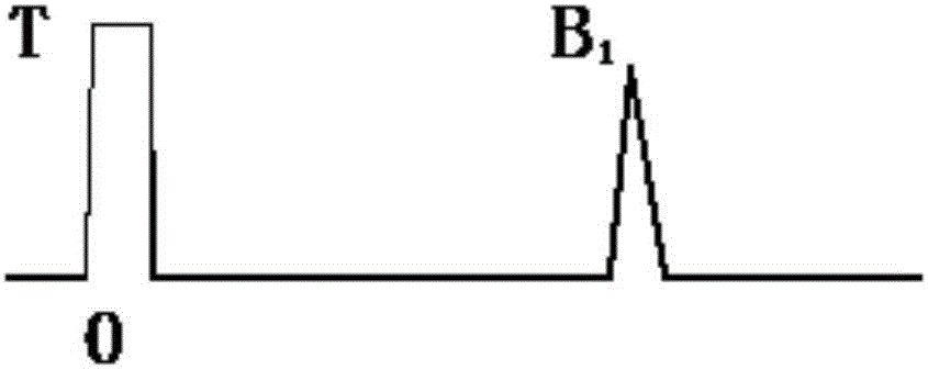
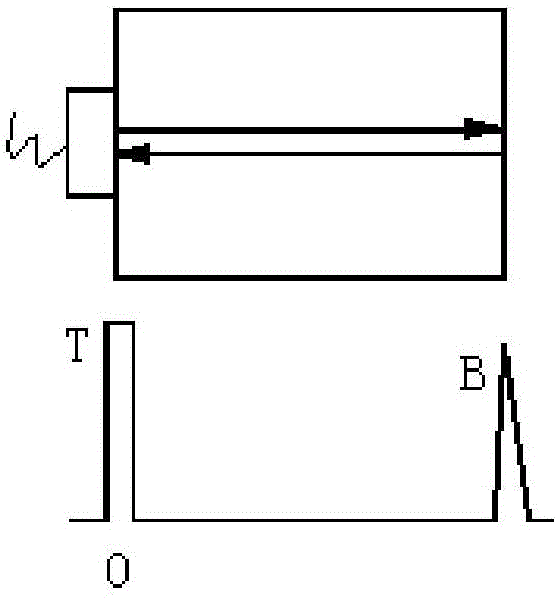
[0096]The sound waves in ultrasonic flaw detection propagate in a beam shape, and there is a certain sound beam spread angle. When a sound wave finds a defect, a damage wave appears, which proves that reflection, refraction, diffraction, scattering and diffraction...


PUM


Abstract

The invention discloses a longitudinal wave normal probe full-beam-path non-blind-area flaw detecting method. The method includes the steps of firstly, arranging a longitudinal wave normal probe on the surface of a to-be-detected workpiece; secondly, setting time baseline conditions so that secondary bottom waves can be adjusted to a position in a certain ratio range of the overall length of a scanning line of an oscilloscope screen with the thickness of the to-be-detected workpiece as the standard; thirdly, setting sensitivity conditions so that sensitivity adjustment can be conducted on the longitudinal wave normal probe according to parameters corresponding to the double value of the thickness of the to-be-detected workpiece; fourthly, sending ultrasonic beams from the longitudinal wave normal probe to detect flaws of the to-be-detected workpiece; fifthly, judging whether flaws exist in the to-be-detected workpiece or not and calculating corresponding flaw information on the basis of the thickness value of the to-be-detected workpiece and the position information of primary bottom waves, secondary bottom waves and flaw echoes in reflected echo signals received by the longitudinal wave normal probe on the scanning line of the oscilloscope screen. The flaws are detected on the basis of the secondary bottom waves, and the effect of full-beam-path non-blind-area flaw detecting is achieved.

Description

technical field [0001] The invention relates to the technical field of ultrasonic flaw detection, in particular to a method for flaw detection with a longitudinal wave straight probe with full sound range and no blind zone. Background technique [0002] The longitudinal wave straight probe flaw detection method is a method of flaw detection using an ultrasonic straight probe to emit longitudinal waves. This method beam is incident vertically on the test piece detection surface and penetrates into the test piece with a constant wave pattern and direction, so it is also called the vertical method. Specifically, it is as follows: Figure 1a-Figure 1b as shown, Figure 1b Mid-bottom echo signal B 1 Located at 80% of the scanning line; specifically, when propagating in the same medium, the longitudinal wave velocity is greater than the velocity of other wave modes, the penetrating ability is strong, and the sensitivity of grain boundary reflection or scattering is poor, so the th...

Claims


Application Information

Patent Timeline
Patent Type & Authority Applications(China)
IPC IPC(8): G01N29/04
CPCG01N29/041
Inventor 曲世发
Owner TEWARE
Why Eureka
Try Eureka