Vehicle-mounted HUD intelligent terminal

A smart terminal and LED light source technology, applied in optical components, optics, instruments, etc., can solve the problems of cost orientation, obvious background white noise, unsatisfactory imaging effect of vehicle HUD smart terminal, etc., and achieve ideal imaging effect

Inactive Publication Date: 2017-01-11
深圳前海智云谷科技有限公司
8 Cites 0 Cited by

AI-Extracted Technical Summary

Problems solved by technology

[0003] In order to ensure the display effect of the car head-up display system (HUD) under strong sunlight, a strong light source is usually required to cooperate with an imaging system (DLP projection imaging system, etc.), and a laser light source or a DLP projector...

Method used

High-brightness liquid crystal display module 5 of the present invention adopts LED dot-matrix surface light source, and power is big, and brightness is bright, and heat dissipation is good, thereby greatly improves the brightness of liquid crystal display 52, can effectively meet the brightness requirement of HUD, and this high-brightness The liquid crystal display module 5 adopts a liquid crystal display, thereby realizing a low-cost automobile HUD solution, which is easy to promote and popularize.
In order to improve the utilization rate of light energy, two layers of brightening films with different directions are placed on the uniform light film 53, so that the scattered light passing through the uniform light film can be modulated into a direction through multiple reflections of the bright film. Consistent direct light, thereby improving the utilization rate of light energy and further improving the brightness of the backlight.
Through the LED surface light source 51 of streng...

Abstract

The invention provides a vehicle-mounted HUD intelligent terminal which comprises a high brightness liquid crystal display module and a HUD imaging screen. The HUD imaging screen comprises a transparent substrate. The transparent substrate has a curvature to form a concave surface. The inner surface of the concave surface is plated with silicon oxide and titanium oxide films to form a concave mirror. The high brightness liquid crystal display module comprises an LED surface light source and an LCD. A brightening film is arranged between the LED surface light source and the LCD. The vehicle-mounted HUD intelligent terminal has the advantages that through the cooperation of the HUD imaging screen and the high brightness liquid crystal display module, an observer can see an amplified image which has a space depth and is superimposed with a scenery behind the concave mirror, the imaging effect is ideal, and the requirement of a user is satisfied.

Application Domain

Optical elements

Technology Topic

Liquid-crystal displayDepth of field +5

Image

  • Vehicle-mounted HUD intelligent terminal
  • Vehicle-mounted HUD intelligent terminal
  • Vehicle-mounted HUD intelligent terminal

Examples

  • Experimental program(1)

Example Embodiment

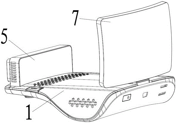
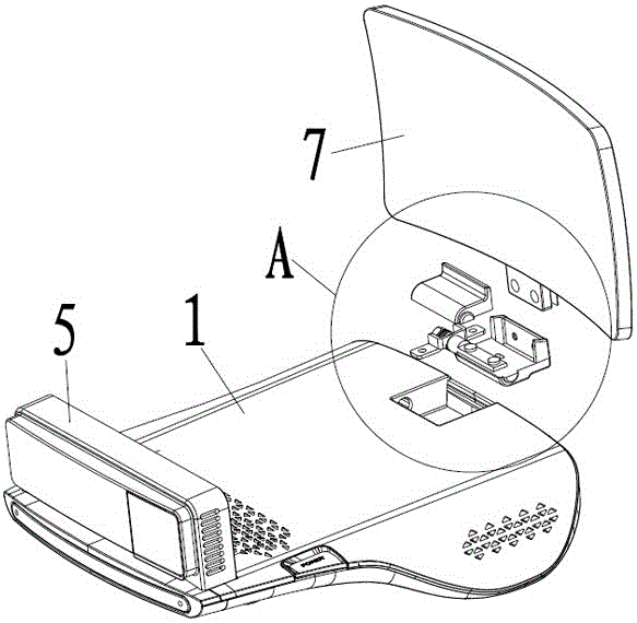
[0022] Such as Figure 5 , 6 As shown, the present invention discloses a vehicle-mounted HUD intelligent terminal, which includes a high-brightness liquid crystal display module 5 and a HUD imaging screen 7. The HUD imaging screen 7 includes a transparent substrate, and the transparent substrate has a curvature to form a concave surface. The inner surface of the concave surface is coated with silicon oxide and titanium oxide film to form a concave mirror; the high-brightness liquid crystal display module 5 includes an LED surface light source 51, a liquid crystal display 52, and the LED surface light source 51 and the liquid crystal display 52 Brightness enhancement film is provided in between.
[0023] As a preferred embodiment of the present invention, three layers of silicon oxide and titanium oxide films are alternately plated on the inner surface of the concave surface to form a concave mirror with magnification and hyperopia effects, as well as reflection and transmission characteristics.
[0024] Alternate plating of each of three layers of silicon oxide and titanium oxide films means: plating in the order of silicon oxide, titanium oxide film, silicon oxide, titanium oxide film, silicon oxide, and titanium oxide film.
[0025] The transparent substrate is PC material or glass or transparent acrylic material.
[0026] In order to improve the visual effect when the vehicle HUD intelligent terminal is placed on the center console of the car, when the driver is viewing information, the visual effect is more transparent, and the outer surface (convex surface) of the concave mirror is plated with anti-reflection that enhances light transmission. The film, the material can be magnesium fluoride or titanium oxide film.
[0027] In order to prevent the adhesion of fingerprints, the fluorine silicon material is deposited on the inner surface and the outer surface of the concave mirror by evaporation method, thereby forming an anti-fouling and anti-grease nano layer to achieve the purpose of anti-fingerprint.
[0028] Through the cooperation of the high-brightness liquid crystal display module of the present invention and the HUD imaging screen 7 (concave mirror) of the present invention, the vehicle-mounted HUD intelligent terminal is placed on the center console of the vehicle to form a head-up display system (HUD).
[0029] Such as Figure 5 As shown, between the LED surface light source 51 and the liquid crystal display 52 are provided two layers of brightness enhancement films with different directions.
[0030] The brightness enhancement film is composed of prisms used to modulate the direction of light refraction and reflection. The two layers of brightness enhancement film with different directions refer to: the first layer of prism arrangement direction is horizontal, and the second layer of prism arrangement direction is vertical; Alternatively, the arrangement direction of the prisms of the first layer is vertical, and the arrangement direction of the prisms of the second layer is horizontal.
[0031] The high-brightness liquid crystal display module 5 further includes a uniform light film 53 which is disposed between the LED surface light source 51 and the brightness enhancement film.
[0032] The high-brightness liquid crystal display module 5 further includes a heat dissipation device 54 which is arranged on the back of the LED surface light source 51.
[0033] The LED surface light source 51 is an LED dot matrix surface light source.
[0034] In order to solve the problem that the brightness of the LED wick is too high, a layer of uniform light film 53 is placed on the LED surface light source 51 to make the backlight light more uniform.
[0035] In order to improve the utilization rate of light energy, two layers of brightness enhancement films with different directions are placed on the homogenization film 53, so that the scattered light passing through the homogenization film can be modulated into direct radiation in the same direction after multiple reflections of the brightness enhancement film. Light, thereby improving the utilization rate of light energy, and further improving the brightness of the backlight.
[0036] The brightness-enhanced LED surface light source 51 becomes a high-brightness liquid crystal display module 5 through the high-transmittance liquid crystal display 52, thereby meeting the requirements of HUD imaging brightness, and achieving a low-cost high-brightness liquid crystal display module 5 to replace the DLP display module the goal of.
[0037] The LED surface light source 51, the heat dissipation device 54, the homogenizing film 53 and the liquid crystal display 52 are installed in the plastic frame 55.
[0038] The high-brightness liquid crystal display module 5 of the present invention adopts an LED dot matrix surface light source, which has high power, bright brightness and good heat dissipation, thereby greatly improving the brightness of the liquid crystal display 52, and can effectively meet the brightness requirements of the HUD, and the high-brightness liquid crystal display module 5Using liquid crystal displays to realize low-cost automotive HUD solutions, which are easy to promote and popularize.
[0039] Such as Figure 1 to 3 As shown, the vehicle-mounted HUD intelligent terminal includes a host 1 and a HUD imaging screen 7, and the vehicle-mounted HUD intelligent terminal also includes an adjustment mechanism that enables the HUD imaging screen 7 to perform angle adjustment on the host 1.
[0040] The adjustment mechanism includes a rotating shaft mechanism that rotates on the host 1, and the HUD imaging screen 7 is connected to the rotating shaft mechanism.
[0041] The host 1 is provided with a cavity 11, and the rotating shaft mechanism is placed in the cavity 11.
[0042] The rotating shaft mechanism includes a rotating shaft 3 and a rotating shaft cover connected to the rotating shaft 3. The rotating shaft cover is placed in the cavity 11, and the HUD imaging screen 7 is installed on the rotating shaft cover.
[0043] The cavity 11 is provided with a hole 12, one end of the rotating shaft 3 is connected with the rotating shaft cover, the other end of the rotating shaft 3 passes through the hole 12 and extends into the main body 1, and the other end of the rotating shaft 3 With blocking piece 4.
[0044] The rotating shaft cover includes an upper rotating shaft cover 6 and a lower rotating shaft cover 8. One end of the rotating shaft 3 is connected to the lower rotating shaft cover 8, and the HUD imaging screen 7 is installed on the lower rotating shaft cover 8, and the upper rotating shaft The cover 6 is installed on the lower cover 8 of the rotating shaft.
[0045] As a preferred embodiment of the present invention, the HUD imaging screen 7 is fixed on the lower cover 8 of the rotating shaft by screws, and one end of the rotating shaft 3 is fixed on the lower cover 8 of the rotating shaft by screws.
[0046] When in use, the rotation of the rotation shaft 3 drives the rotation shaft cover to rotate, so that the HUD imaging screen 7 can be rotated, so as to provide customers with different perspectives, so that users can better experience the interaction of the imaging effect and achieve the best imaging effect.
[0047] Furthermore, the hinge cover of the present invention is placed in the cavity 11, that is, a sinking design is adopted, so that the height of the HUD imaging screen 7 on the host 1 can be reduced.
[0048] The high-brightness liquid crystal display module 5 is located inside the concave mirror, and the display information of the high-brightness liquid crystal display module 5 can be optically magnified into a virtual image in the concave mirror. When the observer is inside the concave mirror, it appears transparent in front of the observer The background superimposed image, that is, the observer can see the enlarged image with spatial depth of field and the real scene behind the concave mirror.
[0049] Such as Figure 1 to 4 As shown, the host 1 is provided with a high-brightness liquid crystal display module 5, the high-brightness liquid crystal display module 5 is installed on the host 1 through a reversing mechanism, and the high-brightness liquid crystal display module 5 is installed with a magnet 103, so The host 1 is provided with a Hall-effect switch 101, the host 1 is provided with a main board 102, and a functional module. The Hall-effect switch 101 is connected to the input end of the main board 102, and the output end of the main board 102 is connected to the function module. The hall effect switch 101 is used to detect whether the high-brightness liquid crystal display module 5 is flipped through the magnet 103, and the hall effect switch 101 sends the detection signal to the main board 102, and the main board 102 receives The detection signal controls the functional module.
[0050] As an embodiment of the present invention, the turning mechanism is a rotating shaft 6, and the high-brightness liquid crystal display module 5 can be flipped through the rotating shaft 6, so that when the car owner does not need a HUD display, the method of turning the high-brightness liquid crystal display module 5 , Put the high-brightness liquid crystal display module 5 away.
[0051] The functional module includes an audio module, and the audio module is connected to the output terminal of the main board 102.
[0052] The audio module includes an audio power amplifier module 104 and a speaker 105, the input end of the audio power amplifier module 104 is connected to the main board 102, and the output end of the audio power amplifier module 104 is connected to the speaker 105.
[0053] The functional module includes a display screen backlight module 106, and the output end of the main board 102 is connected to the display screen backlight module 106. Specifically, the display screen backlight module 106 is an LED surface light source.
[0054] The host 1 is provided with a HUD imaging screen 7 for receiving images projected by the high-brightness liquid crystal display module 5. The HUD imaging screen 7 is a concave mirror. When in use, the high-brightness liquid crystal display module 5 projects the image onto the concave mirror. , So as to realize the HUD display.
[0055] When the car owner does not need the HUD display, put the high-brightness LCD module 5 away, the Hall effect switch 101 is close to the magnet 103, the Hall effect switch 101 outputs a low level to the main board 102, and the main board 102 turns off the display backlight module 106 And the audio power amplifier module 104, to realize off display and off sound. When the high-brightness liquid crystal display module 5 is turned on, the Hall-effect switch 101 is far away from the magnet 103, the Hall-effect switch 101 outputs a high level to the main board 102, and the main board 102 turns on the display backlight module 106 and the audio power amplifier module 104 to realize the display and Turn on the sound.
[0056] The high-brightness liquid crystal display module 5 of the present invention can be turned over, and as the high-brightness liquid crystal display module 5 is turned over, the sound room and the display can be opened and closed accordingly, which brings convenience to the user.
[0057] The above content is a further detailed description of the present invention in combination with specific preferred embodiments, and it cannot be considered that the specific implementation of the present invention is limited to these descriptions. For those of ordinary skill in the technical field to which the present invention belongs, several simple deductions or substitutions can be made without departing from the concept of the present invention, which should be regarded as falling within the protection scope of the present invention.

PUM

no PUM

Description & Claims & Application Information

We can also present the details of the Description, Claims and Application information to help users get a comprehensive understanding of the technical details of the patent, such as background art, summary of invention, brief description of drawings, description of embodiments, and other original content. On the other hand, users can also determine the specific scope of protection of the technology through the list of claims; as well as understand the changes in the life cycle of the technology with the presentation of the patent timeline. Login to view more.

Similar technology patents

Carbon quantum dot two-photon fluorescent dye for ultrafast cell staining

PendingCN114736675Agood biocompatibilityGood imaging effect
Owner:SUZHOU INST OF BIOMEDICAL ENG & TECH CHINESE ACADEMY OF SCI

Optical lens and imaging equipment

ActiveCN113900238Aincrease the amount of lightGood imaging effect
Owner:JIANGXI LIANCHUANG ELECTRONICS CO LTD

Smart television cabinet

InactiveCN112956842Aeasy to useGood imaging effect
Owner:重庆知遨科技有限公司

Wide-visual field compressed holographic imaging system and method

ActiveCN108008615AGood imaging effectExpand the imaging area
Owner:TSINGHUA UNIV

Laser marker, detection equipment and detection control method

PendingCN114441560Aavoid missingGood imaging effect
Owner:IMDETEK

Classification and recommendation of technical efficacy words

  • Good imaging effect

Imaging method for inverse synthetic aperture radar of high-speed moving targets

ActiveCN104502912AGood imaging effect
Owner:NANJING UNIV OF SCI & TECH

Prism device applied to periscopic lens module and periscopic lens module

ActiveCN110187465AWide imaging angleGood imaging effect
Owner:AAC OPTICS SOLUTIONS PTE LTD

Holographic projection box and imaging method and interaction method thereof

InactiveCN106154697AGood viewing effectGood imaging effect
Owner:SHENZHEN ZHONGSHU CREATIVE CULTURE & MEDIA TECH CO LTD

Ray chromatography imaging method for refracted waves

InactiveCN102096099AImaging steps are simpleGood imaging effect
Owner:武侯区巅峰机电科技研发中心
Why Eureka
Try Eureka