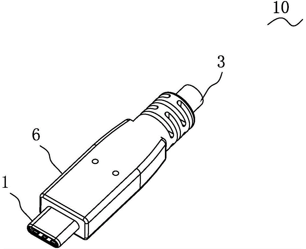
Cable connector

A cable connector and connector technology, applied in the direction of connection, fixed connection, conductive connection, etc., can solve the problems of cumbersome welding process, prone to defective products, dense pad spacing, etc., to reduce crosstalk and flatten Impedance characteristics, effect of reducing the number of wires

Active Publication Date: 2017-01-11
DONGGUAN MOLEX INTERCONNECT +1
View PDF7 Cites 7 Cited by
  • Summary
  • Abstract
  • Description
  • Claims
  • Application Information

AI Technical Summary

Problems solved by technology

The conductive circuit layer on the component board of this micro-USB connector is one-to-one and straightly extends forward and backward. When this micro-USB connector is connected to the cable, it needs to be welded on the rear of the component board with the same number of conductive terminals. However, due to the dense spacing of the rear pads on the conductive line layer, the process of soldering the connecting wires is quite troublesome and prone to defective products
In addition, there is no shielding design between the conductive circuit layer on the upper surface of the circuit board of this connector and the conductive circuit layer on the lower surface of the circuit board, and it is easy to interfere with each other during high-speed data transmission, resulting in crosstalk problems.

Method used


Image

  • Cable connector
  • Cable connector
  • Cable connector

Examples


Embodiment Construction

[0061] While the invention may readily manifest in different forms of embodiments, only a few specific embodiments have been shown in the drawings and will be described in detail in this specification, with the understanding that the specification should be considered as the These are exemplary illustrations of the principles of the invention and are not intended to limit the invention to what is described herein.

[0062] Thus, a feature indicated in this specification will be used to describe one of the features of an embodiment of the invention, not to imply that every embodiment of the invention must have the described feature. Furthermore, it should be noted that this specification describes a number of features. Although certain features may be combined to illustrate possible system designs, these features may also be used in other combinations not explicitly described. Thus, the illustrated combinations are not intended to be limiting unless otherwise stated.

[0063]...


PUM


Abstract

The invention provides a cable connector, which comprises a male connector, a circuit board fixed at the rear part of the male connector and a cable, wherein the cable is correspondingly welded to the circuit board; the circuit board comprises an insulating substrate, a first surface conducting layer, a first internal conducting layer, a first grounded shield layer, a second grounded shield layer, a second internal conducting layer and a second surface conducting layer; the first surface conducting layer, the first internal conducting layer, the first grounded shield layer, the second grounded shield layer, the second internal conducting layer and the second surface conducting layer are sequentially arranged on the insulating substrate at intervals; a public power pool area is arranged on the first internal conducting layer; the first grounded shield layer and the second grounded shield layer fully extend on the circuit board to partition the first surface conducting layer and the second surface conducting layer at the upper side and the lower side; and a blank area is formed at a vertical projection position, corresponding to a back bonding pad, for transmitting a high-speed differential signal, of the first surface conducting layer, of the internal conducting layer. The cable connector is especially suitable for high-speed signal transmission.

Description

technical field [0001] The invention relates to a cable connector, in particular to a cable connector suitable for high-speed data transmission and easy to manufacture. Background technique [0002] Chinese patent CN201420267847.1 discloses a miniature USB reversible male connector, which includes an upper terminal unit, a lower terminal unit, a metal shield, two anti-vibration units, a hollow insulating body, a shell and a component board. The upper terminal unit, the lower terminal unit and the metal shielding sheet are fixedly connected together and inserted into the insulating body. The metal shielding sheet is arranged between the upper terminal unit and the lower terminal unit. The upper terminal unit includes an integrally formed upper base and an upper terminal group, the upper terminal group is embedded in the upper base, and its two ends protrude out of the upper base. The rear section of the upper base is provided with a first installation part. The lower termi...

Claims


Application Information

Patent Timeline
Patent Type & Authority Applications(China)
IPC IPC(8): H01R9/03H01R12/57
Inventor 梁升萧广荣李有爱聂刚
Owner DONGGUAN MOLEX INTERCONNECT
Why Eureka
Try Eureka