
Motor heat dissipation structure

A motor and structure technology, applied in the direction of electromechanical devices, electrical components, mechanical equipment, etc., can solve the problems of inability to directly transport the forward airflow, danger, and the motor is easy to accumulate heat.

Inactive Publication Date: 2017-01-11
周文三
View PDF6 Cites 4 Cited by
  • Summary
  • Abstract
  • Description
  • Claims
  • Application Information

AI Technical Summary

Problems solved by technology

[0002] In the field of today's technology industry, the motor is a very commonly used power object. However, whether it is a large motor that provides high power or a small motor that provides low power, after the motor starts the rotor to run, it is very easy to accumulate in the motor housing. High heat, due to the lack of a heat dissipation structure that can timely eliminate the high temperature generated by the motor operation, the high heat accumulated inside the motor will cause the magnetic force of the magnet to decline, and the operating efficiency of the motor will also gradually decrease. When the temperature rises to After a certain level, the insulation of the enameled coil in the armature will be destroyed, which will cause a short circuit of the enameled coil and burn the entire motor, and even lead to other dangers
In order to prevent this kind of deficiency, the technology commonly used at present will attach a heat dissipation blade fan to one end of the central rotating shaft of the motor, so as to suppress the temperature that the motor increases rapidly during operation, but this technology only allows the heat dissipation blade fan to advance The air flow blows through the outer surface of the motor casing, and in fact, the forward airflow cannot be directly transported into the inside of the motor casing, and it cannot effectively dissipate heat from the inside of the motor in a timely manner. The disadvantage of easy heat accumulation is still insurmountable

Method used


Image

  • Motor heat dissipation structure
  • Motor heat dissipation structure
  • Motor heat dissipation structure

Examples


Embodiment Construction

[0034] Since the operating principle and internal related structures of the motor are already quite common and publicly known technologies, they will not be described in detail in this specification.

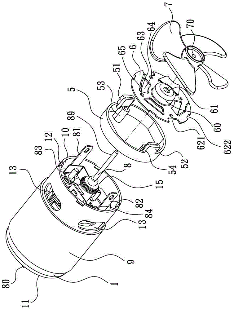
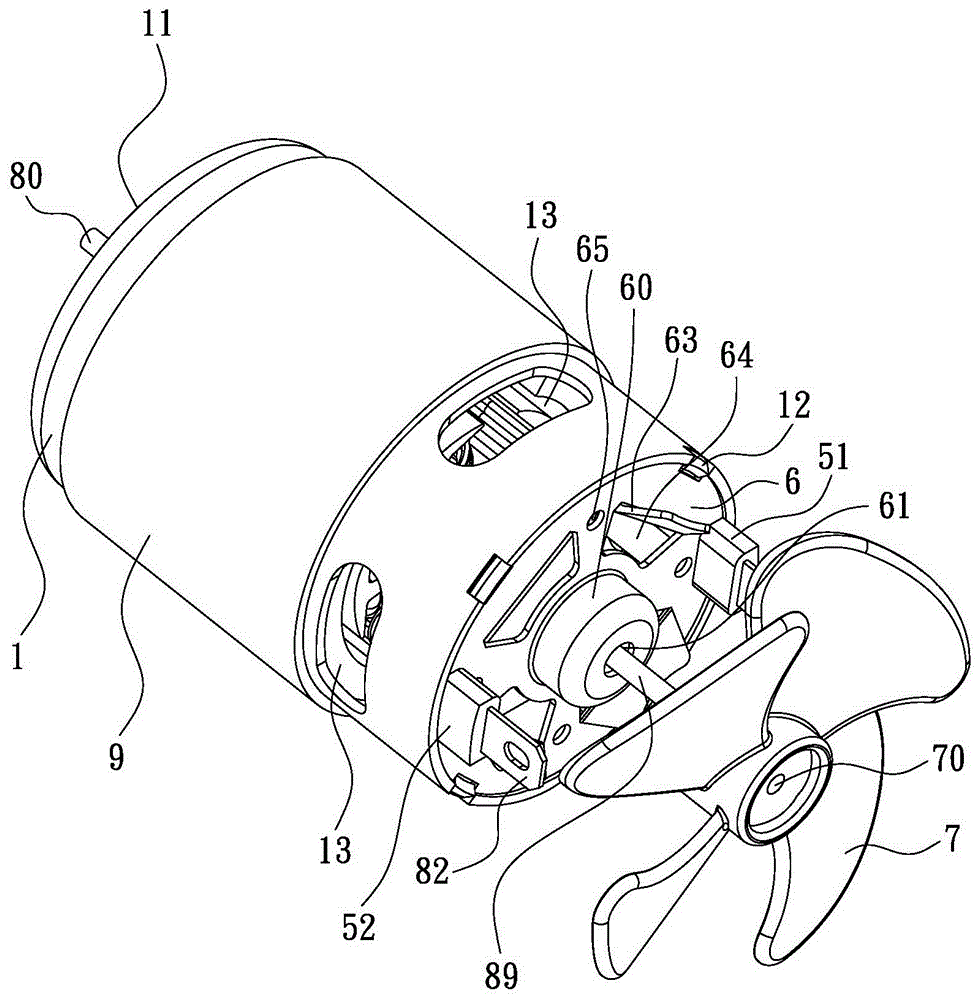
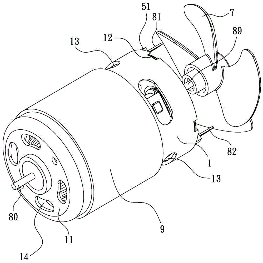
[0035] Please refer to Figure 1 to Figure 3 , the present invention is a heat dissipation structure of a motor, which basically includes a housing 1 with an internal space 15, a forward opening 10 is formed at one end of the housing 1, and a plurality of corresponding openings are arranged on the edge of the forward opening 10. Spaced positioning buckles 12, the other end of the housing 1 forms a closed rearward wall 11, the rearward wall 11 is pierced with a plurality of isolated air outlets 14, and is provided on the circumferential surface of the housing 1. There is at least one convection hole 13 completely through, so that the inside of the motor housing 1 and the outside of the motor housing 1 can generate air flow. The housing 1 is provided with the necessary elements o...


PUM


Abstract

A motor heat dissipation structure is provided; revolution airflow formed by a cooling fan installed in the motor side in operation can be quickly led into the motor housing to play the role of heat dissipation, so that the motor is not easy to accumulate heat inside; the front end of the motor housing is provided with a front cover having a plurality of wind guide plates and a drain port, and the circular swirling forward airflow generated when the cooling fan rotates can be directly blocked by the wind guide plates of the front cover, and can directly enter the motor housing by the drain port; the outer part of the circular swirling forward air flow can also be blown from the outer periphery of the housing to the outer surface of the housing, so that the outer housing is also dissipated at the same time, thus forming multiple heat dissipation paths, and exerting more effective heat dissipation; the inner side of the motor housing cannot accumulate heat, so the motor operational maximum output power can be realize , thus enhancing the motor operating efficiency, and also extending the life of the motor.

Description

technical field [0001] The invention relates to a heat dissipation structure of a motor. Background technique [0002] In the field of today's technology industry, the motor is a very commonly used power object. However, whether it is a large motor that provides high power or a small motor that provides low power, after the motor starts the rotor to run, it is very easy to accumulate in the motor housing. High heat, due to the lack of a heat dissipation structure that can timely eliminate the high temperature generated by the motor operation, the high heat accumulated inside the motor will cause the magnetic force of the magnet to decline, and the operating efficiency of the motor will also gradually decrease. When the temperature rises to After a certain level, the insulator of the enameled coil in the armature will be damaged, which will cause a short circuit of the enameled coil and burn the entire motor, and even lead to other dangers. In order to prevent this kind of d...

Claims


Application Information

Patent Timeline
Patent Type & Authority Applications(China)
IPC IPC(8): H02K9/06H02K5/04
CPCH02K5/04H02K9/06H02K5/207F04B35/04F04B39/066H02K9/28
Inventor 周文三
Owner 周文三
Learn More