Synchronization method and apparatus in interference unit, and interference unit

A technology of jammers and synchronization signals, which is applied in the field of jammers and can solve problems such as difficulties in synchronous tracking and processing of jammers

Active Publication Date: 2017-01-11
CHINA MOBILE COMM GRP CO LTD
View PDF5 Cites 2 Cited by
  • Summary
  • Abstract
  • Description
  • Claims
  • Application Information

AI Technical Summary

Problems solved by technology

However, if the frame headers of the TD-LTE system between multiple frequency bands are not synchronized, it will be difficult to track the jammer synchronously, because the jammer needs to scan back and forth between multiple frequency bands in order to track the synchronous multiple channels at the same time. TD-LTE system on frequency bands

Method used


Image

  • Synchronization method and apparatus in interference unit, and interference unit
  • Synchronization method and apparatus in interference unit, and interference unit
  • Synchronization method and apparatus in interference unit, and interference unit

Examples


Embodiment 1

[0045] An embodiment of the present invention provides a synchronization method in a jammer. The method is applied to a jammer. The functions implemented by the method can be implemented by calling a program code from a processor in the jammer. Of course, the program code can be stored in a computer storage medium , it can be seen that the jammer includes at least a processor and a storage medium.

[0046] Figure 5 It is a schematic diagram of the implementation flow of the synchronization method in the jammer according to the embodiment of the present invention, as shown in Figure 5 As shown, the synchronization methods in this jammer include:

[0047] Step 501, tracking the synchronization signal on the reference frequency band to obtain the current frame head position of the reference frequency band;

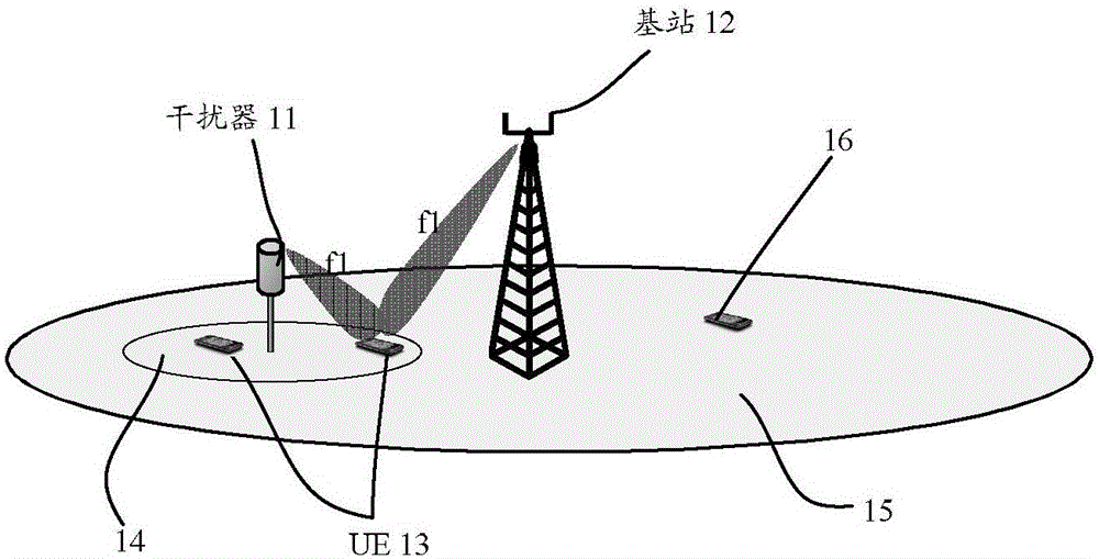
[0048] Here, the reference frequency band is one or more frequency bands in the communication system supported by the jammer. For the convenience of implementation, in th...

Embodiment 2

[0058] Based on the foregoing first embodiment, the embodiment of the present invention provides a synchronization method in a jammer, the method is applied to a jammer, and the functions realized by the method can be realized by calling a program code by a processor in the jammer. Of course, the program The code can be stored in a computer storage medium. It can be seen that the jammer includes at least a processor and a storage medium.

[0059] Image 6 It is a schematic diagram of the implementation flow of the synchronization method in the jammer in Embodiment 2 of the present invention, as shown in Image 6 As shown, the synchronization methods in this jammer include:

[0060] Step 601, after the jammer is powered on, control the transmission link of the jammer to keep off;

[0061] Here, in addition to the processor, the jammer also includes a transmission link for transmitting interference signals. After the jammer is powered on, the processor first controls the trans...

Embodiment 3

[0079] Based on the aforementioned embodiments, this embodiment of the present invention provides a synchronization device in a jammer. The tracking unit, determination unit, acquisition unit, and sending unit in the device can all be implemented by a processor in the jammer; Realize by specific logic circuit; In the process of specific embodiment, processor can be central processing unit (CPU), microprocessor (MPU), digital signal processor (DSP) or field programmable gate array (FPGA) etc. .

[0080] Figure 7 It is a schematic diagram of the composition and structure of the synchronization device in the jammer in Embodiment 3 of the present invention, as Figure 7 As shown, the apparatus 700 includes a tracking unit 701, a determining unit 702, an acquiring unit 703, and a sending unit 704, wherein:

[0081] The tracking unit 701 is configured to track the synchronization signal on the reference frequency band, and obtain the current frame head position of the reference f...


PUM


Abstract

The invention discloses a synchronization method in an interference unit. The method comprises: a synchronization signal on a reference frequency band is tracked and a current frame head position of the reference frequency band is obtained; according to a time difference of a frame head position of a communication system supported by the interference unit at each frequency band and the frame head position of the reference frequency band as well as a current frame head position of the reference frequency band, a current frame head position of each frequency band is determined; a frame structure of each frequency band is obtained; and on the basis of the current frame head position of each frequency band and a corresponding frame structure, a synchronous control signal is sent, wherein the synchronous control signal is used for controlling a transmitting link in the interference unit to transmit an interference signal. In addition, the invention also discloses a synchronization apparatus in an interference unit and an interference unit.

Description

technical field [0001] The invention relates to jammer technology, in particular to a synchronization method and device in a jammer, and a jammer. Background technique [0002] In some sensitive places such as party and government organs or school examination rooms, for purposes such as confidentiality, it is necessary to block normal mobile phone communications in specific areas or places. In this case, jammers are generally deployed near the target area. figure 1 It is a schematic diagram of the network architecture in the prior art, such as figure 1 As shown, generally speaking, the jammer 11 is a high-power wireless signal transmitter, and the jammer 11 continuously transmits high-power interference or noise signals on the same downlink frequency as the base station 12 . Therefore, the user equipment (UE) 13 in the target area 13 will also be strongly interfered by the interferer 11 while receiving normal base station signals, thereby causing the UE 13 to be unable to m...

Claims


Application Information

Patent Timeline
Patent Type & Authority Applications(China)
IPC IPC(8): H04J3/06H04J3/16H04L27/26
Inventor 王大鹏闫渊程广辉张敏
Owner CHINA MOBILE COMM GRP CO LTD
Why Eureka
Try Eureka