Connection method and communication device, and communication system

A technology of a communication device and a connection method, applied in the fields of connection, communication device and communication system, can solve problems such as failure to obtain data and deterioration of data distribution efficiency.

Inactive Publication Date: 2017-01-11
FUJITSU LTD
5 Cites 0 Cited by

AI-Extracted Technical Summary

Problems solved by technology

This leads to a situation where a communication device in a poor communication state continues to search for a connection destination without participating in the data distribution system wit...

Abstract

A connection method and a communication device, and a communication system are provided; a first communication device compares communication quality between a target communication device selected from among communication devices having a possibility of becoming a connection destination and the first communication device, with a quality threshold. The first communication device obtains the quality threshold as a function of data reception quality in the target communication device and a number of communication devices to which connections were attempted by the first communication device excluding the target communication device. The first communication device sets the quality threshold as a detection threshold for detecting an opportunity to change a connection destination when the communication quality is equal to or higher than the quality threshold. The first communication device determines a second communication device with relatively high communication quality with the first communication device to be a connection destination used until the communication quality between the second and first communication devices falls below the detection threshold.

Application Domain

Connection managementStar/tree networks

Technology Topic

Telecommunications equipmentCommunication quality +3

Image

  • Connection method and communication device, and communication system
  • Connection method and communication device, and communication system
  • Connection method and communication device, and communication system

Examples

  • Experimental program(1)

Example Embodiment

[0034]
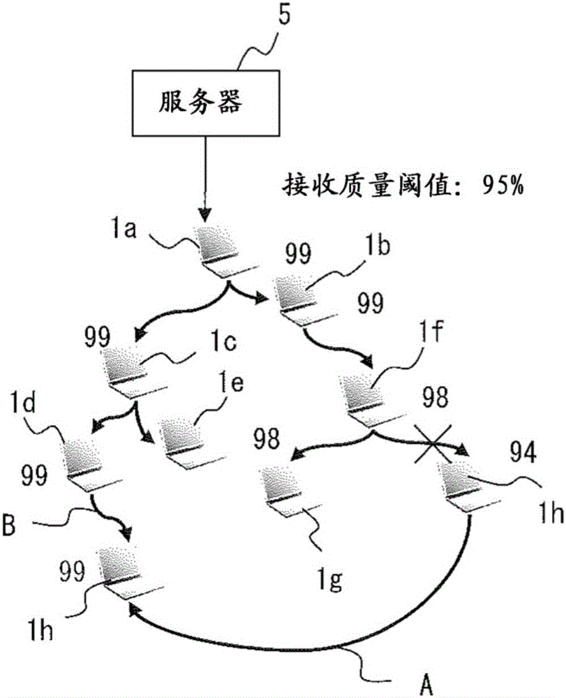
[0035] Hereinafter, an example of processing performed when the communication device 10 newly participates in the data distribution system will be explained as the acquisition of candidates for connection destinations in the data distribution system, the calculation of reception quality, and the determination of connection destinations. Hereinafter, in order to clearly express which of the communication devices 10 is performing processing, the same character as the identifier assigned to the communication device 10 may be added to the end of the reference numeral. For example, the acquisition unit 21h refers to the acquisition unit 21 included in the communication device 10h.
[0036] (1) Acquisition of candidates for connection destination
[0037] Figure 5 An example of a method of acquiring information of a connection destination is shown. Figure 5 The network shown in includes a server 5 and three groups G1 to G3, however, any number of groups can exist in the network. Each group includes any number of communication devices 10, any number being at least one, and each group includes one group manager node (GMN) 52. The group manager node 52 is determined by sending a control packet from the server 5, etc., to the communication device 10 that will become the new group manager node 52 when the group is generated, wherein the control packet requests the communication device 10 to operate as the group manager Node 52. Each communication device 10 in the group except for the group manager node 52 periodically reports to the group manager node 52 of the group to which the communication device 10 belongs, the number of communication devices 10 connected to the communication device 10, and that the communication device 10 can be updated. Number of connections formed, quality of reception, etc. Note that each communication device 10 recognizes the total number of devices that can be connected to the communication device 10 and the number of devices that the communication device 10 is currently connected to, and calculates the number of devices that can be newly connected based on these values. Therefore, each group manager node 52 can periodically obtain information of other communication devices 10 in the group to which the group manager node 52 belongs.
[0038] Figure 5 The table T1 shown in is the information held by the group manager node 52a on each communication device 10 in the group G1. Table T1 stores the ID, IP (Internet Protocol) address, and whether there may be a new connection for each device in the group. The example of the table T1 shows the following situation: the group G1 includes communication devices 10a to 10c, the new communication device 10 can be connected to the communication devices 10a and 10c, and the connection of the new communication device 10 to the communication device 10b is not allowed.
[0039] Figure 5 The following is exemplified: the group manager node 52a of the group G1 and the group manager node 52b of the group G2 are directly connected to the server 5 and the group manager node 52c of the group G3 is connected to the group manager node 52a. note, Figure 5 The case where the group manager node 52 is connected to another group manager node 52 or the server 5 is illustrated, however, the group manager node 52 may also be connected to devices other than another group manager node 52 or the server 5.
[0040] When the communication device 10 tries to participate Figure 5 In the data distribution system shown in, the communication device 10 sends a participation request packet P1 to the server 5 (arrow A1). The participation request packet P1 includes a header and information indicating that the communication device 10 requests it to participate in the data distribution system.
[0041] The server 5 transmits the received participation request packet P1 to the group manager node 52 including the group of nodes connected to the server 5. in Figure 5 In the example shown in the server 5, the server 5 transmits the participation request packet P1 to the group manager node 52a and the group manager node 52b (arrow A2). When another group is connected to the downstream side of the group manager node 52, the group manager node 52 transmits the participation request packet P1 to the group manager node 52 of the group on the downstream side. For example, the group manager node 52a transmits the participation request packet P1 to the group manager node 52c of the group G3 (arrow A3). Through this process, the participation request packet P1 is transmitted to the group manager nodes 52 of all groups in the data distribution system.
[0042] The group manager node 52 that has obtained the participation request packet P1 reports to the transmission source of the participation request packet P1 information about the communication device 10 with which a new connection can be established among the communication devices 10 in the group including the group manager node 52 itself. For example, the group manager node 52a transmits the fact that a connection can be established with the communication devices 10a and 10c and the IP addresses of the communication devices 10a and 10c by referring to the table T1 to the communication device 10 that sent the participation request packet P1 (arrow A4). The group manager node 52a also reports the reception quality in each device that is a candidate for the connection destination to the communication device 10 that transmitted the participation request packet P1. Will refer to Image 6 To explain how to get the reception quality. Similar to the group manager node 52a, the group manager nodes 52b and 52c of other groups can also send to the communication device 10 sending the participation request packet P1 that the group of each of the group manager nodes 52b and 52c can establish a connection therewith. The IP address of the device and the quality of reception in such a device (arrow 5).
[0043] The communication device 10 receives the following packet from each group manager node 52, which reports the information of the communication device 10 that can be connected. Since the received packet is obtained via the receiver 11, the acquisition unit 21 of the communication device 10 extracts information of the device to be a candidate for the connection destination from the received packet and stores the information in the connection destination candidate list 31.
[0044] (2) Method of calculating reception quality
[0045] Image 6 An example of a method of calculating reception quality is shown. By reference Image 6 , An explanation of an example of the following method will be given: calculating the reception quality by a device that is in the data distribution system or is trying to participate in the data distribution system. in Image 6 In the example shown in, the device that distributes the distribution data transmits data packets and control packets to the device that is the distribution destination. Note that an example of a device that distributes distribution data includes a communication device 10 that transmits distribution data to another communication device 10 in addition to the server 5. in Image 6 In the example shown in P11, the data packet distributed by the data distribution system includes image data. As depicted in P11, the data packet includes an IP header, a UDP (User Datagram Protocol) header, a serial number, and allocation-target image data. The sequence number indicates the order of the image data being distributed. Note that the sequence number is included in the packet as information included in the payload.
[0046] Meanwhile, the control packet is a packet sent to report the number of data packets sent during a prescribed time period, and is sent for every prescribed time period (ΔT). As depicted in P12, the control packet includes an IP header, a TCP (Transmission Control Protocol) header, and control data. The control data includes: the value of the first number of the sequence number included in the data packet sent immediately after the transmission of the previous control packet, the value of the last number of the sequence number included in the sent data packet, and The number of packets sent.
[0047] Image 6 The sequence SEQ1 shown in shows an example of transmission timing for control packets and data packets in an exemplary case where data is distributed from the communication device 10f to the communication device 10h. In the sequence SEQ1, the sending of a control packet is indicated by a solid arrow, and the sending of a data packet is indicated by a dotted arrow.
[0048] Assume, for example, that the relay processing unit 27f of the communication device 10f has generated a control packet at the start of data distribution in order to transmit the control packet to the communication device 10h via the transmitter 12f (arrow A11). Since the data packet has not been transmitted before the transmission of the control packet indicated by arrow A11, the control packet transmitted from the communication device 10f as indicated by arrow A11 includes the following information.
[0049] The first serial number: 0
[0050] Last serial number: 0
[0051] Number of packets sent: 0
[0052] Assume the processing performed by the relay processing unit 27f of the communication device 10f, after which data packets with serial numbers 1 to 100 are transmitted from the communication device 10f to the communication device 10h. The quality calculation unit 22h of the communication device 10h obtains the data packet via the receiver 11h so as to store the serial number extracted from the obtained data packet. In this example, it is assumed that the communication device 10h receives a data packet with a serial number of 1 and a serial number of 3 to 100. Then, because serial number 1 and serial numbers 3 to 100 are stored in the quality calculation unit 22h, the number of serial numbers stored accordingly is 99.
[0053] When the transmission period (ΔT) for the control packet has elapsed since the time of the previous transmission of the control packet, the communication device 10f generates a control packet including the following information, and transmits the packet to the communication device 10h (arrow A12).
[0054] The first serial number: 1
[0055] Last serial number: 100
[0056] Number of packets sent: 100
[0057] The quality calculation unit 22h in the communication device 10h obtains the control packet via the receiver 11h, and obtains the number of data packets transmitted between the previously received control packet and the data packet transmitted at that moment, and also obtains the serial number. When 100 data packets are transmitted between the received control packet shown by arrow A11 and the received control packet shown by arrow 12, the quality calculation unit 22h only saves the sequence numbers of 99 data packets. In response to this situation, the quality calculation unit 22h calculates the ratio of the received data packets to the total number of transmitted data packets as the reception quality. In this example, with respect to 100 data packets sent, 99 data packets have been received, and the quality calculation unit 22h accordingly calculates 99% as the reception quality. Since the calculation of the reception quality is completed, the quality calculation unit 22h resets the number of received packets, and continues to calculate the reception quality in a similar manner.
[0058] It is assumed that, for example, after receiving the control packet as shown by arrow A12, the communication device 10f transmits data packets with serial numbers 101 to 200 to the communication device 10h. It is also assumed that the communication device 10h receives data packets with serial numbers 101 to 180, but does not receive packets with serial numbers 181 and later. Then the quality calculation unit 22h stores the fact that 80 packets with serial numbers 101 to 180 are received after the reception of the control packet as shown by arrow A12.
[0059] The communication device 10f generates a control packet including the following information in order to transmit the control packet to the communication device 10h (arrow A13).
[0060] The first serial number: 101
[0061] The last serial number: 200
[0062] Number of packets sent: 100
[0063] When 100 data packets are sent between the control packet received as indicated by arrow A12 and the control packet received as indicated by arrow A13, the quality calculation unit 22h only receives 80 data packets. Then, the quality calculation unit 22h calculates 80% as the reception quality, because 80 data packets have been received relative to 100 data packets. Note that the transmission interval ΔT for control packets is determined according to the implementation.
[0064] (3) Confirmation of connection destination
[0065] Figure 7 An example of a communication method according to an embodiment is shown. In the following, it is assumed that the distribution system of the data sent by the server 5 includes a plurality of devices including communication devices 10a to 10g. note, Figure 7 Only some communication devices 10 in the data distribution system are shown. for Figure 7 In the communication devices 10a to 10e shown in, the reception quality in each device and the value of the threshold for determining whether to change the communication destination are represented by numeric strings with diagonal lines between the numeric strings. The value on the left of the diagonal line represents the reception quality of the communication device 10, and the value on the right of the diagonal line represents the threshold used by the communication device 10. The reception quality or the threshold may vary depending on the communication environment. For example, the communication device 10a uses 100% as both the reception quality and the threshold. This causes the communication device 10a to change the connection destination when the reception quality has fallen below 100%. The communication devices 10c and 10d have 100% as the reception quality and 99% as the threshold value, and the communication devices 10c and 10d will not change the connection destination even when the reception quality has become 99.5%.
[0066] Figure 7 The communication devices 10h-1 to 10h-3 in show a situation where a communication device 10h trying to participate in the data distribution system is connected to a candidate that has been reported as a connection destination. By reference Figure 7 to Figure 9 , An explanation will be given of the processing performed when the communication device 10 newly participating in the data distribution system determines the connection destination.
[0067] The acquiring unit 21h in the communication device 10h first generates a participation request requesting participation in the data distribution system, and sends the participation request to the server 5 via the transmitter 12h. Then, by reference Figure 5 In the illustrated processing, the information that the communication device 10h can be connected to the communication device 10 is reported to the communication device 10h. The acquisition unit 21h in the communication device 10h uses the received packet to generate the connection destination candidate list 31h. In the following description, it is assumed that the information of the five communication devices 10 (ie, the communication device 10b and the communication devices 10d to 10g) is reported to the connection destination candidate list 31h. In the following description, it is assumed that the communication devices 10b, 10d, and 10e are assigned IP addresses 10.0.0.2, 192.168.10.2, and 192.168.10.3. Similarly, it is also assumed that the communication devices 10f and 10g are assigned the IP addresses 192.168.11.2 and 192.168.11.3. In addition, the IP address assigned to the communication device 10h is 192.168.10.100.
[0068] Figure 8 with Picture 9 Examples of the connection destination candidate list 31 and the quality list 33 are shown. Figure 8 The connection destination candidate list 33h-1 shown in is an example of the connection destination candidate list 31h generated by the acquisition unit 21h by using the received packet. In the connection destination candidate list 31h-1, the priority order, IP address, and reception quality of each of the obtained connection candidates are recorded.
[0069] Since receiving the information of a plurality of devices of the communication device 10 as candidates for the connection destination of the communication device 10h, the acquisition unit 21h determines the connection destination as the communication device 10h for each of the reported connection destination candidates Priority order of places. In the example of the connection destination candidate list 31h-1, the acquisition unit 21h gives the communication device candidates that are the communication device candidates and the communication devices 10 belonging to the same sector as the candidate including the communication device 10h more than the communication devices 10 belonging to other sectors. The priority order is the higher priority order. In addition, when a plurality of communication devices 10 are candidates for connection destinations in the same section, the communication device 10 with higher reception quality is given a higher priority order. Note that the higher the priority order, the smaller the value indicating the priority order. For the section that does not include the communication device 10, the acquiring unit 21h determines that the greater the bit length of the part where the IP address of the communication device 10h and the network address of the section are consistent, the greater the distance from the section to the section to which the communication device 10h belongs. near. For the devices in the section that does not include the communication device 10h, the acquiring unit 21h gives priority order in the following manner: the closer the device section is to the communication device 10h, the higher the priority order given to these sections. in Figure 8 In the example shown in the communication devices 10d, 10e, and 10h are included in the same section. In addition, although the communication devices 10f and 10g are included in the same section, both belong to a section different from the section including the communication device 10h. In addition, the section including the communication devices 10f and 10g is determined to be a section closer to the communication device 10h than the section to which the communication device 10b belongs. Therefore, for the candidates of the connection destination of the communication device 10h, the priority order is set in the order of the communication devices 10d, 10e, 10f, 10g, and 10b. Note that in Figure 8 with Picture 9 In order to facilitate the understanding of the correspondence between the IP address and the communication device 10, each IP address is followed by a bracketed reference sign of the device that assigns the IP address.
[0070] Since the determination of the priority order is completed, the comparison unit 23h selects the communication device 10 as the connection destination from the devices in the connection destination candidate list 31h-1, and reports the selected communication to the quality calculation unit 22h and the connection processing unit 25h 装置10。 Device 10. Hereinafter, the device selected as the connection destination when the communication quality is measured may also be referred to as the "target device". The connection processing unit 25h starts communication with the target device via the receiver 11h and the transmitter 12h. Assume that, for example, the comparison unit 23h has selected the communication device 10d having the highest priority order (the priority order is 1) in the connection destination candidate list 31h-1 as the target device. Then, the connection processing unit 25h transmits a control packet to and receives the control packet from the communication device 10d via the transceiver 13h, thereby connecting the communication device 10h to the communication device 10d. The connection between the communication device 10h and the communication device 10d is Figure 7 Is shown as communication device 10h-1.
[0071] The comparison unit 23h calculates the threshold value to be compared with the reception quality with respect to the target device by using equation (1), where Thn is the threshold value for comparison with the reception quality, and n is the threshold value to be selected as the target device. The value of the priority order associated with the device, RQn is the reception quality in the device selected as the target device, and α is a constant.
[0072] Thn=RQn-α×(n-1)...(1)
[0073] The constant α is a constant used when the threshold value becomes smaller in response to determining that the communication quality with the device attempting to connect at that time is lower than the threshold value. The constant α is a positive value determined according to the communication quality of the network. When, for example, the communication quality in the data distribution system is high, the constant α is set to be relatively small, and when the communication quality in the data distribution system is low, the larger value is set to the constant α. Note that (n-1) multiplied by the constant α is the number of communication devices 10 attempted to connect before the target device. As a result, the increase in the number of devices attempting to connect increases the value subtracted from the reception quality in the communication device 10 as the connection destination when calculating the threshold, so that the threshold is likely to be a smaller value.
[0074] for Figure 7 As an example of the communication device 10h-1 shown in, the target device is the communication device 10d with the highest priority order (the priority order is 1) in the connection destination candidate list 31h-1. Therefore, the comparison unit 23h uses the reception quality (RQ1) associated with the communication device 10d and the number of devices that the communication device 10h attempts to connect with other than the communication device 10d to calculate the value for comparison with the reception quality according to equation (2) Threshold (Th1).
[0075] Th1=RQ1-α×(1-1)=RQ1=100...(2)
[0076] According to equation (2), the value of the threshold Th1 is the same as the reception quality in the communication device 10d. in Figure 7 , The fact that the threshold Th1 is equal to the reception quality in the communication device 10d is determined by the arrow drawn from the reception quality in the communication device 10d toward the threshold used in the communication device 10h-1 and the difference (-0) between the two Said. Because the threshold Th1 is 100%, when the reception quality of the data received from the communication device 10d in the communication device 10h is 100%, the comparison unit 23h determines that the connection state with respect to the communication device 10d is good enough for the communication device 10d to be Data distribution source.
[0077] At the same time, when the communication device 10h has been connected to the communication device 10d, the communication device 10h starts to receive a data packet including distributed data and a control packet from the communication device 10d. The quality calculation unit 22h obtains the packet received from the communication device 10d via the receiver 11h, and calculates the reception quality. Refer to above Image 6 Described to calculate the reception quality. The quality calculation unit 22h records the obtained reception quality together with the information of the communication destination in the quality list 33h. in Figure 8 In the example of the quality list 33h-1 shown in, the reception quality obtained by using the communication device 10d as the connection destination is 94%.
[0078] The comparison unit 23h refers to the quality list 33h-1 ( Figure 8 ) To obtain the reception quality when receiving data from the communication device 10d, and compare the obtained received value with the threshold Th1. When the threshold Th1 is 100%, the reception quality when receiving data from the communication device 10d is 94%. Therefore, the comparison unit 23h determines that the connection state between the communication device 10d and the communication device 10h is not good enough to use the communication device 10d as a data distribution source. Then, the comparison unit 23h deletes the communication device 10d from the connection destination candidate list 31h-1 to generate the connection destination candidate list 31h-2 ( Figure 8 ).
[0079] Next, assume that the comparison unit 23h has selected the communication device 10e having the highest priority order (priority order 2) in the connection destination candidate list 31h-2 as the target device. Also suppose as Figure 7 As shown in the communication device 10h-2 in, the communication device 10h has been connected to the communication device 10e through the processing performed by the connection processing unit 25h.
[0080] The comparison unit 23h uses the reception quality (RQ2) obtained in the communication device 10e and the number of devices that the communication device 10h other than the communication device 10e tries to connect to, in order to calculate a threshold value for comparison with the reception quality according to equation (3) (Th2). In the following, it is assumed that the constant α is 2. Th2=RQ2-α×(n-1)
[0081] =99-2×(2-1)=97...(3)
[0082] According to equation (3), the threshold Th2 is a value smaller than the reception quality in the communication device 10e. in Figure 7 The fact that the threshold Th2 is smaller than the reception quality in the communication device 10e is determined by the arrow drawn from the reception quality in the communication device 10e toward the threshold used in the communication device 10h-2 and the difference (-2) between the two Said. Because the threshold Th2 is 97%, when the reception quality of the data received from the communication device 10e in the communication device 10h is equal to or greater than 97%, the comparison unit 23h determines that the connection state of the communication device 10e is sufficiently good to be able to be used for the communication device 10e As a data distribution source.
[0083] When the communication device 10h has been connected to the communication device 10e, the communication device 10h starts receiving data packets and control packets including distribution data from the communication device 10e. The quality calculation unit 22h calculates the reception quality. In this example, it is assumed that the reception quality of data received from the communication device 10e in the communication device 10h is 93%. Because the quality calculation unit 22h records the obtained information of the reception quality in the quality list 33h, the quality list 33h is updated from the state shown in the quality list 33h-1 to the state shown in the quality list 33h-2 ( Figure 8 ).
[0084] The comparison unit 23h uses the quality list 33h-2 to obtain the reception quality when receiving data from the communication device 10e, and compares the obtained received value with the threshold Th2. When the threshold Th2 is 97%, the reception quality when receiving data from the communication device 10e is 93%. Therefore, the comparison unit 23h determines that the connection state between the communication device 10e and the communication device 10h is not good enough to use the communication device 10e as a data distribution source, and deletes the communication device 10e from the connection destination candidate list 31h-2 . Therefore, the connection destination candidate list 31h is updated as shown in the connection destination candidate list 31h-3 ( Figure 8 ).
[0085] Next, assume that the comparison unit 23h has selected the communication device 10f with the highest priority order (priority order 3) in the connection destination candidate list 31h-3 as the target device. It is also assumed that the communication device 10h has been connected to the communication device 10f by the processing performed by the connection processing unit 25h.
[0086] The comparison unit 23h uses the reception quality (RQ3) obtained in the communication device 10f and the number of devices that the communication device 10h other than the communication device 10f tries to connect to, in order to calculate a threshold value for comparison with the reception quality according to equation (4) (Th3).
[0087] Th3=RQ3-α×(n-1)
[0088] =100-2×(3-1)=96...(4)
[0089] Because the threshold Th3 is 96%, when the reception quality of the data received from the communication device 10f in the communication device 10h is equal to or greater than 96%, the comparison unit 23h determines that the connection state with respect to the communication device 10f is sufficiently good to be able to be used for the communication device 10f. As a data distribution source.
[0090] When the communication device 10h has been connected to the communication device 10f, the quality calculation unit 22h calculates the reception quality. In this example, it is assumed that the reception quality of data received from the communication device 10f in the communication device 10h is 89%. Since the quality calculation unit 22h records the obtained information of the reception quality in the quality list 33h, the quality list 33h is updated from the state shown in the quality list 33h-2 to the state shown in the quality list 33h-3 ( Figure 8 ).
[0091] The comparison unit 23h uses the quality list 33h-3 to obtain the reception quality when receiving data from the communication device 10f, and compares the obtained received value with the threshold Th3. When the threshold Th3 is 96%, the reception quality when receiving data from the communication device 10f is 89%. Therefore, the comparison unit 23h determines that the connection state between the communication device 10f and the communication device 10h is not good enough to use the communication device 10f as a data distribution source, and deletes the communication device 10f from the connection destination candidate list 31h-3 . Therefore, the connection destination candidate list 31h is updated as shown in the connection destination candidate list 31h-4 ( Picture 9 ).
[0092] Next, assume that the comparison unit 23h has selected the communication device 10g having the highest priority order (priority order 4) in the connection destination candidate list 31h-4 as the target device. It is also assumed that the communication device 10h has been connected to the communication device 10g by the processing performed by the connection processing unit 25h.
[0093] The comparison unit 23h uses the reception quality (RQ4) obtained by the communication device 10g and the number of devices that the communication device 10h other than the communication device 10g attempts to connect to, in order to calculate the threshold (RQ4) for comparison with the reception quality according to equation (5) Th4).
[0094] Th4=RQ4-α×(n-1)
[0095] =97-2×(4-1)=91...(5)
[0096] Because the threshold Th4 is 91%, when the reception quality of the data received from the communication device 10g in the communication device 10h is equal to or greater than 91%, the comparison unit 23h determines that the connection state of the communication device 10g is sufficiently good to be able to be used for the communication device 10g As a data distribution source.
[0097] When the communication device 10h has been connected to the communication device 10g, the quality calculation unit 22h calculates the reception quality. In this example, it is assumed that the reception quality of data received from the communication device 10g in the communication device 10h is 90%. Since the quality calculation unit 22h records the information of the obtained reception quality in the quality list 33h, the quality list 33h changes from the state shown in the quality list 33h-3 ( Figure 8 ) Is updated to the status shown in the quality list 33h-4 ( Picture 9 ).
[0098] The comparison unit 23h uses the quality list 33h-4 to compare the reception quality when data is received from the communication device 10g with the threshold Th4. When the threshold Th4 is 91%, the reception quality when receiving data from the communication device 10g is 90%. Therefore, the comparison unit 23h determines that the connection state between the communication device 10g and the communication device 10h is not good enough to use the communication device 10g as a data distribution source, and deletes the communication device 10g from the connection destination candidate list 31h-4 . Therefore, the connection destination candidate list 31h is updated as shown in the connection destination candidate list 31h-5 ( Picture 9 ).
[0099] Next, assume that the comparison unit 23h has selected the communication device 10b with the highest priority order (priority order 5) in the connection destination candidate list 31h-5 as the target device. It is also assumed that the communication device 10h has been connected to the communication device 10b by the processing performed by the connection processing unit 25h.
[0100] The comparison unit 23h uses the reception quality (RQ5) obtained by the communication device 10b and the number of devices that the communication device 10h other than the communication device 10b tries to connect to, in order to calculate the threshold value (RQ5) for comparison with the reception quality according to equation (6) Th5).
[0101] Th5=RQ5-α×(n-1)
[0102] =98-2×(5-1)=90...(6)
[0103] According to equation (6), the value of the threshold Th5 is smaller than the reception quality in the communication device 10b. in Figure 7 The fact that the value of the threshold Th5 is less than the reception quality in the communication device 10b is determined by the arrow drawn from the reception quality in the communication device 10b toward the threshold used in the communication device 10h-3 and the difference between the two (-8 )To represent. Because the threshold Th5 is 90%, when the reception quality of the data received from the communication device 10b in the communication device 10h is 90%, the comparison unit 23h determines that the connection state with the communication device 10b is sufficiently good and can be used to treat the communication device 10b as Data distribution source.
[0104] When the communication device 10b has been connected to the communication device 10b, the quality calculation unit 22h calculates the reception quality. In this example, it is assumed that the reception quality of data received from the communication device 10b in the communication device 10h is 91%. Since the quality calculation unit 22h records the information of the obtained reception quality in the quality list 33h, the quality list 33h changes from the state shown in the quality list 33h-4 ( Picture 9 ) Is updated to the status as shown in the quality list 33h-5 ( Picture 9 ).
[0105] The comparison unit 23h uses the quality list 33h-5 to compare the reception quality when data is received from the communication device 10b with the threshold Th5. When the threshold Th5 is 90%, the reception quality when receiving data from the communication device 10b is 91%. Therefore, the comparison unit 23h determines that the connection state between the communication device 10b and the communication device 10h is good enough to be able to use the communication device 10b as a data distribution source. Therefore, the comparison unit 23h outputs to the setting unit 24h and the connection processing unit 25h the fact that the connection destination that results in the reception quality of at least the threshold Th5 for the current use has been found.
[0106] The setting unit 24h sets the currently used threshold Th5 as the detection threshold. The connection processing unit 25h uses the quality list 33h-5 in order to select the communication device 10 with the highest reception quality as the connection destination from the devices whose reception quality has been measured at that time. The quality list 33h-5 indicates that the reception quality obtained using the communication device 10d as the connection destination is the highest among the devices for which the reception quality is measured, and therefore the connection processing unit 25h selects the communication device 10d as the connection destination. The connection processing unit 25h disconnects the communication with the communication device 10b that is currently being connected, and connects the communication device 10h to the communication device 10d.
[0107] After the connection destination is determined, the quality calculation unit 22h continues the calculation of the reception quality. In addition, the connection processing unit 25h compares the reception quality calculated by the quality calculation unit 22h with the detection threshold to monitor whether the connection destination is appropriate. When the reception quality calculated by the quality calculation unit 22h has fallen below the detection threshold, the connection processing unit 25h determines to change the connection destination, and requests the acquisition unit 21h to acquire candidates for the connection destination. In response to a request from the connection processing unit 25h, the acquisition unit 21h acquires the information of the connection destination similar to the case of participating in the data distribution system, and accordingly changes the connection destination by processing similar to the processing explained above.
[0108] When the communication device 10h is connected to any communication device in the communication device 10, the data packet including the allocated data is output not only to the quality calculation unit 22h but also to the data processing unit 26h. Because the allocated data is processed in the data processing unit 26h, the processing result of the data is provided to the user of the communication device 10h via an output device (such as a display device, a speaker device, etc.) as needed. In addition, when another communication device 10h has been connected to the communication device 10h, the data packet including the allocated data is also output to the relay processing unit 27h. The relay processing unit 27h transmits the data packet including the allocated data to the communication device 10 connected to the communication device 10 via the transmitter 12h.
[0109] Picture 10 It is a flowchart illustrating an example of the communication method according to the embodiment. note, Picture 10 The processing shown in is an example and the order of steps S31 and S32 may be changed, for example. In addition, step S35 may be omitted to cause a change so that the processing of step S36 is performed in all cases. In addition, the order of steps S26 and S27 may be changed, or steps S26 and S27 may be performed in parallel.
[0110] The acquiring unit 21 sends a connection request to the server 5 (step S21). The receiver 11 receives the packet including the information of the connection destination candidate, and outputs the packet to the acquisition unit 21 (step S22). The acquisition unit 21 generates a connection destination candidate list 31 based on the acquired information. The comparison unit 23 determines whether the connection destination candidate list 31 includes the communication device 10 included in the section to which the device of the comparison unit 23 belongs (step S23). When the connection destination candidate list 31 does not include the communication device 10 included in the section to which the device of the comparing unit 23 belongs, the comparing unit 23 selects a region whose address has the same longest part as the address of the device of the comparing unit 23 Segment (No in step S23, step S24). When the connection destination candidate list 31 includes the communication device 10 included in the section to which the device of the comparing unit 23 belongs, the comparing unit 23 selects the section to which the device of the comparing unit 23 belongs (Yes in step S23). The comparison unit 23 selects a candidate with high reception quality in the selected section as a target device (step S25). The comparison unit 23 sets the threshold value for comparison with the reception quality to a value obtained by subtracting the product of the number of retries and a constant value (constant α) from the value of the reception quality of the target device (step S26). Note that the number of retries is the number of devices that attempted to connect before the connection of the target device being processed. The connection processing unit 25 connects the device of the connection processing unit 25 to the target device (step S27). After that, the quality calculation unit 22 measures the reception quality and records the obtained value in the quality list 33 (steps S28 and S29). The comparison unit 23 determines whether the reception quality is equal to or greater than a threshold value (step S30). When the reception quality is equal to or greater than the threshold value, the connection processing unit 25 determines whether the currently obtained reception quality is the maximum value among the values ​​of the reception quality recorded in the quality list 33 (YES in step S30, step S35). When the currently obtained reception quality is the maximum value among the values ​​of the reception quality recorded in the quality list 33, the connection process is terminated (YES in step S35).
[0111] When the current reception quality is not the maximum value in the quality list 33, the connection processing unit 25 disconnects the communication with the current connection destination, and also connects the target device causing the maximum value of the reception quality to the device of the connection processing unit 25 (step No in S35, step S36).
[0112] When it is determined in step S30 that the reception quality is not equal to or greater than the threshold value, the comparison unit 23 removes the current target device from the connection destination candidate list 31 and increases the number of retries by one (steps S31 and S32). When the connection destination candidate list 31 is not empty, the comparison unit 23 returns to step S23 (NO in step S33). When the connection destination candidate list 31 is empty, the setting unit 24 sets the maximum value in the quality list 33 as the threshold value (YES in step S33, step S34). After the processing in step S34, the processing in step S35 and after step S35 is executed.
[0113] As described above, according to the method of the embodiment, the communication device 10 attempting to participate in the data distribution system changes the detection for determining whether to change the connection destination according to the number of devices that the communication device 10 attempts to connect to and the reception quality in the connection destination. Threshold. Therefore, before the connection destination is finally determined, the larger the number of devices that the communication device 10 attempts to connect to, the smaller the detection threshold of the communication device 10 can be set. Since it is not easy for the communication device 10 that uses a smaller value as the detection threshold to have its reception quality lower than the detection threshold, its connection destination does not change frequently during the distribution of data. In other words, according to the present embodiment, the communication device 10 that is in a poor communication state with respect to another device can even prevent a situation in which the frequency of searching for a connection destination is too high and obstructing communication by setting a smaller value as the detection threshold. The device 10 receives the distribution data. In addition, the method according to the embodiment allows the communication device 10 to receive distribution data from a connection destination having a relatively good communication state among devices whose reception quality has been measured.
[0114] In the above description, for ease of understanding, an example in which the communication device 10 newly participates in the data distribution system has been used, but the communication device 10 whose reception quality is lower than the detection threshold also determines the connection destination through similar processing.
[0115] Picture 11 An improved example of the data distribution system using the method according to the embodiment is shown. Picture 11 Case C1 in shows an example of a network in a case where a data distribution system has been formed across multiple departments of the company. The communication device 10x and the communication device 10y are located in the department A, and the communication device 10m, the communication device 10n, and the communication device 10p are located in the department C. Note that it is assumed that the communication device 10s, 10t, or 10u is not located in any department. Note that in Picture 11 Here, the server 5 is not shown, but the communication device 10x may directly receive the distribution data from the server 5 or may receive the distribution data via another device. The communication device 10x transmits the received data to the communication device 10s and the communication device 10y. The communication device 10s transmits the received data to the communication device 10t and the communication device 10u, and the communication device 10y transmits the received data to the communication device 10m. Furthermore, it is assumed that the communication device 10m transmits the data received from the communication device 10y to the communication device 10n and the communication device 10p.
[0116] It is assumed that the communication state between departments A and C deteriorates during communication on the route shown in case C1. Assume that when the communication state deteriorates, the reception quality in each communication device 10 located in department C is 92% for the communication devices 10m and 10n and 91% for the communication device 10p. In addition, it is assumed that the reception quality for the communication devices 10x and 10y located in the department A is 99%. When it is assumed that the detection threshold is set to 95% in all the communication devices 10 in the situation shown in the case C1, the reception quality is lower than the threshold for all the communication devices 10m, 10c, and 10p. Therefore, the communication devices 10m, 10n, and 10p start the process of disconnecting the communication with the current connection destination, and detecting the connection destination from which the distributed data is to be received.
[0117] Assume that the communication device 10m passes the reference Figure 5 to Figure 10 The described processing uses the reception quality in the connection destination and the number of devices attempted to connect before connecting to the target device selected as the connection destination, and makes the threshold smaller in response to each increase in the number of connection failures. It is also assumed that when the detection threshold in the communication device 10m has become 90%, the above situation results in the establishment of a connection with the communication device 10y.
[0118] Picture 11 Case C2 in shows a case where the communication device 10m is connected to the communication device 10y when the detection threshold is set to 90% in the communication device 10m. In case C2, the threshold value and reception quality being used are presented for each device located in department A or C. The reception quality is to the left of the diagonal line, and the detection threshold is to the right of the diagonal line. In the state shown in the case C2, for example, "92/90" appears as the reception quality of the communication device 10m and the connection destination threshold value because the communication device 10m has a reception quality of 92%. After the communication device 10m sets the communication device 10y as the connection destination again, the communication device 10n and the communication device 10p also search for the connection destination through a process similar to that performed by the communication device 10m. Therefore, in the example shown in case C2, when the detection threshold is 92% and the reception quality has become 92%, the communication device 10n determines the communication device 10m as the connection destination. When the connection destination threshold is 90% and the reception quality has become 91%, the communication device 10p determines the communication device 10m as the connection destination.
[0119] As reference Picture 11 As explained, the communication device 10m in a poor communication state can use the method according to the embodiment to lower the detection threshold, and thus can receive data relatively stably by avoiding frequent searching for the connection destination. In addition, because the communication device 10m stably receives data even when the reception quality is not so good, the communication device 10m can also transmit data to the communication device 10n and the communication device 10p connected to the communication device 10m. As described above, according to the method of the embodiment, even if the communication state of the communication device 10 located on the boundary between the base stations is poor, the communication device 10 lowers the detection threshold according to its own communication environment to allow relatively stable acquisition of detection. The connection destination of the data. This avoids the situation that for the communication device 10 located on the boundary between the base stations, a poor communication state prevents data from being distributed to the entire base station including the communication device 10, and thus the efficiency of data distribution can be improved.
[0120]
[0121] Note that the embodiment is not limited to the above embodiment but allows various modifications. A modified example will be described below.
[0122] In the above description, the threshold value calculated by using the reception quality of the connection destination is only compared with the reception quality obtained during the connection to the connection destination, however, the following modification can be made: a threshold value can be compared with that in the quality list 33 All reception quality values ​​are compared. When the reception quality of the connection destination is worse than the reception quality using a different communication device 10, the above modification makes it possible to find the connection destination in a shorter time period than the above method.
[0123] Picture 12 It is a flowchart illustrating an example of a communication method according to a modified example. The processing in steps S41 to S49 is similar to that by reference Picture 10 The processing in steps S21 to S29 described. In addition, the processing in steps S51 to S56 is similar to that by referring to Picture 10 The processing in steps S31 to S36 described. In step S50, the comparison unit 23 determines whether the quality list 33 includes a reception quality greater than the threshold used in the current process. When the quality list 33 has a reception quality greater than the threshold used in the current processing, the processing in step S55 and after step S55 is performed. When the quality list 33 does not have a reception quality greater than the threshold used in the current processing, the processing in step S51 and after step S51 is performed.
[0124] In addition, different methods can be used to determine the order of priority depending on the implementation. For example, the reception quality may be used to determine the priority order regardless of the section to which the communication device 10 belongs.
[0125] As described above, the method according to the embodiment realizes efficient data distribution.

PUM

no PUM

Description & Claims & Application Information

We can also present the details of the Description, Claims and Application information to help users get a comprehensive understanding of the technical details of the patent, such as background art, summary of invention, brief description of drawings, description of embodiments, and other original content. On the other hand, users can also determine the specific scope of protection of the technology through the list of claims; as well as understand the changes in the life cycle of the technology with the presentation of the patent timeline. Login to view more.
Why Eureka
Try Eureka