Special Sliding Rotary Support

A technology of slewing bearings and bearing bases, which is applied in packaging and other directions, can solve the problems of increased wear of intermediate support bushings, frequent replacement, and increased load of augers, so as to reduce equipment use costs, restrain flexible deformation, and ensure concentricity Effect

Inactive Publication Date: 2017-01-18
台州恒投工贸有限公司
View PDF0 Cites 2 Cited by
  • Summary
  • Abstract
  • Description
  • Claims
  • Application Information

AI Technical Summary

Problems solved by technology

[0004] 1. Because it uses three supports to ensure the concentricity of the auger, these three supports interfere with the auger blades, and the auger blades can only be cut off, which leads to the fact that the blades of the two segmented auger cannot be formed from bottom to top Continuously, when the material is conveyed here, it can only be conveyed upward through the "material pushing" method. The lower auger squeezes the material through the cutting part, and the height of the material is pushed up to the upper auger blade.
Since the auger with a higher lifting height has at least 2 to 5 intermediate supports, the material will be squeezed 2-5 times, and the friction between the material and the pipe wall will increase by 2-5 times, which results in the axial power of the vertical auger. will increase, and the cost ratio will deteriorate
[0005] 2. Since the auger is a rotating body and the intermediate support is fixed, it is similar to a sliding bearing structure. When the material squeezes through the intermediate support, some materials will penetrate into the gap of the support surface. When the gap is filled, The shaft of the auger will be "locked", and the load of the whole auger will be increased until it stops due to overload
[0006] When there is only one intermediate support, adjusting the auger to ensure concentricity can be a good solution, but when the conveying height is high, at least 2-5 are required, which greatly increases the difficulty of adjustment. When several intermediate supports are different After centering, the intermediate support sleeve will wear more and needs to be replaced frequently, which increases the maintenance cost of the equipment

Method used


Image

  • Special Sliding Rotary Support
  • Special Sliding Rotary Support
  • Special Sliding Rotary Support

Examples


Embodiment Construction

[0020] The following will clearly and completely describe the technical solutions in the embodiments of the present invention with reference to the accompanying drawings in the embodiments of the present invention. Obviously, the described embodiments are only some, not all, embodiments of the present invention. Based on the embodiments of the present invention, all other embodiments obtained by persons of ordinary skill in the art without making creative efforts belong to the protection scope of the present invention.

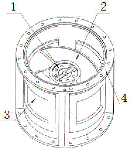
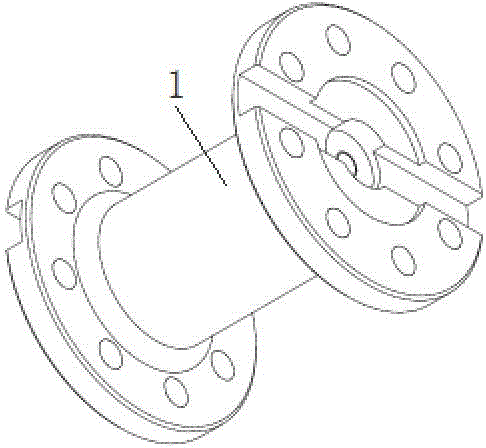
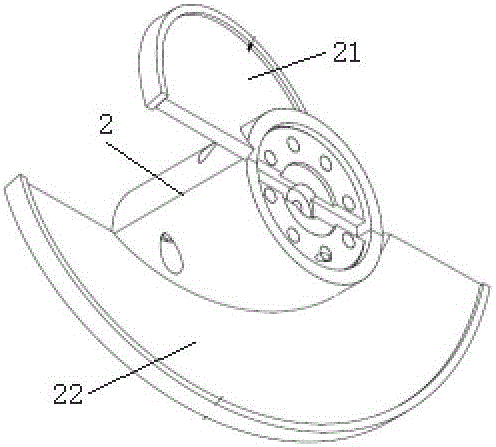
[0021] see Figure 1-6 , an embodiment provided by the present invention: a special sliding slewing bearing, including a coupling 1 and a bearing base 4, a half auger cage 2 is installed on the outside of the coupling 1, and the half auger cage 2. It is composed of half half auger cage one 21 and half half auger cage two 22. The edges of half half auger cage one 21 and half half auger cage two 22 are welded with wear-resistant The insert 23, the bearing outer...


PUM


Abstract

The invention discloses a special sliding slewing bracket, including shaft coupling and bearing base. On the outside of the shaft coupling there fixed a hough auger retainer, which is made up of no. 1 half hough auger retainer and no. 2 half hough auger retainer, the edges of both are equipped with wear-resisting insert. Bearing outer ring is installed on the outside of the bearing base, and the shaft coupling and Hough auger retainer are located inside bearing base. This invention can effectively guarantee the concentricity of the lay and simplicity of adjustment, efficiently constraining the flexible deformation generated by the packing auger; free of maintenance or any lubricating medium, reducing service cost, simple in structure and easy to operate.

Description

technical field [0001] The invention relates to the technical field of slewing bearings, in particular to a special sliding slewing bearing. Background technique [0002] At present, in the long-length vertical auger conveyor, when the vertical auger is lifted more than 5 meters, the vertical auger needs to be segmented auger, which is formed by connecting two or several auger sections through the middle section . The conveying principle of the vertical auger is that after a certain centrifugal force is formed on the material through a high speed, the material will adhere to the inner wall of the conveyor under the action of the centrifugal force. At this time, the auger lifts the material to a certain height for discharge. The auger with a higher lifting height is similar to a slender shaft. At a higher speed, it will produce a certain amount of flexible deformation. If it is not restrained, its radial jump will cause the vertical auger to vibrate, and even the auger will ...

Claims


Application Information

Patent Timeline
IPC IPC(8): B65G33/32
CPCB65G33/32
Inventor 奚冬明王学龙莫忠良
Owner 台州恒投工贸有限公司
Why Eureka
Try Eureka