Dual motor lifting stand column

A technology of lifting columns and dual motors, applied in the direction of lifting devices, controlling mechanical energy, electrical components, etc., can solve the problem of high installation distance, achieve the effect of small operating current, fast lifting, and avoid the effect of unable to lift

Inactive Publication Date: 2017-01-18
ZHEJIANG JIECHANG LINEAR MOTION TECH
View PDF6 Cites 2 Cited by
  • Summary
  • Abstract
  • Description
  • Claims
  • Application Information

AI Technical Summary

Problems solved by technology

[0003] The technical problem to be solved by the present invention is to provide a dual-motor lifting column to solve the problem of high installation distance in existing lifting columns

Method used


Image

  • Dual motor lifting stand column
  • Dual motor lifting stand column

Examples


Embodiment 1

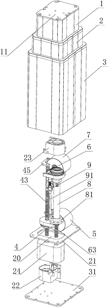
[0021] Such as figure 1 As shown, a double-motor lifting column includes an inner tube 1, a middle tube 2 and an outer tube 3. The inner tube 1 is inserted into the middle tube 2, and the middle tube 2 is inserted into the outer tube 3. It also includes an inner tube end plate 11, a middle tube Tube end plate 21, outer tube end plate 31, first gear box 22 and second gear box 23, the first gear box 22 is arranged on the middle tube end plate 21, and the first transmission system 4 is connected to the first gear box 22 , the output end of the first transmission system 4 is connected with the first gear box 22, the input end of the first transmission system 4 is connected with the first motor 5, the first motor 5 is fixedly connected on the middle tube end plate 21, the middle tube end plate 21 is arranged on the bottom end of the middle pipe 2, the second gear box 23 is provided with the second transmission system 6, the output end of the second transmission system 6 is connecte...

Embodiment 2

[0026] A double-motor elevating column as described in Embodiment 1, this embodiment has the following differences: the first transmission system and the second transmission system are arranged as a ball screw and nut transmission structure, and the nut is arranged on the ball screw, Both the middle tube and the inner tube are fixedly connected to the nut, and the ball screw is respectively connected to the first motor and the second motor through the reduction gear box, and the rotation of the ball screw is controlled by the motor, driving the nut to go up and down on the ball screw, respectively. Lifting of middle tube and inner tube.

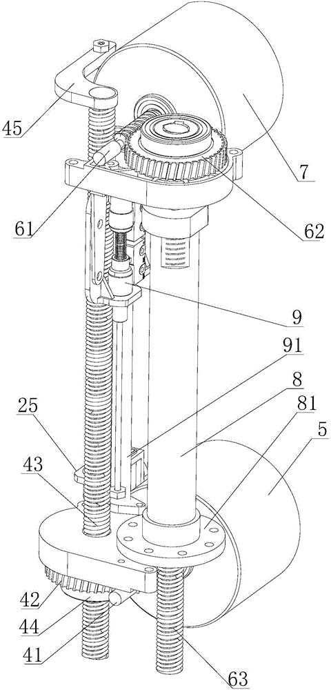
[0027] During use, the first motor 5 drives the first worm screw 41 to rotate, drives the first worm wheel 42 and the first screw mandrel 43 to rotate, thereby realizing that the first gear box 22 does linear motion on the first screw mandrel 43, and the first gear box 22 Drive the middle tube end plate 21 to rise and fall synchronously, so a...


PUM


Abstract

The invention relates to a dual motor lifting stand column and belongs to the technical field of lifting devices. The problem that lifting stand columns are low in transmission efficiency is solved. According to the technical scheme for solving the problem, the dual motor lifting stand column mainly comprises an inner pipe, a middle pipe, an outer pipe, an inner pipe end plate, a middle pipe end plate, a first gear case and a second gear case. The first gear case is connected with a first transmission system. The output end of the first transmission system is connected with the first gear case. The input end of the first transmission system is connected with a first motor. The first motor is fixedly connected to the middle pipe end plate. The second gear case is provided with a second transmission system. The output end of the second transmission system is connected with the middle pipe end plate. The input end of the second transmission system is connected with a second motor. The second motor is fixedly connected to the inner pipe end plate. The dual motor lifting stand column has the advantages that the first motor and the second motor are mounted on the middle pipe end plate and the inner pipe end plate correspondingly, the locating distance of the gear cases and the locating distance of the stand column can coincide, and the purpose of shortening the locating distances is achieved.

Description

technical field [0001] The invention relates to a column, in particular to a dual-motor lifting column. Background technique [0002] Lifting columns can be widely used in tables, chairs, hospital beds, etc. in homes or medical places. Taking electric lifting tables as an example, the existing electric lifting tables mainly consist of two or more independent lifting columns and connecting fixtures and synchronous The controller is composed of a screw nut drive to realize linear motion, and a synchronous controller is used to realize synchronous lifting of two or more columns. When the existing lifting column is lifted at the second level, the lifting column is lifted by a transmission system. The lifting stroke cannot be well controlled, the transmission efficiency is low, and the installation height of the existing lifting column is too high, which cannot maximize the utilization of space. Contents of the invention [0003] The technical problem to be solved by the prese...

Claims


Application Information

Patent Timeline
Patent Type & Authority Applications(China)
IPC IPC(8): B66F13/00H02K7/116
CPCB66F13/00H02K7/116
Inventor 陆小健胡仁昌程云山裘凯峰马勇
Owner ZHEJIANG JIECHANG LINEAR MOTION TECH
Why Eureka
Try Eureka