Swing lever press cloth handle

A handle and rod technology, applied in textiles, papermaking, knitting, etc., can solve the problems of high labor intensity and low production efficiency, and achieve the effects of labor-saving operation, high production efficiency and novel structure

Inactive Publication Date: 2017-10-20
DAYE XINGYUN ELECTROMECHANICAL TECH RES INST
View PDF10 Cites 0 Cited by
  • Summary
  • Abstract
  • Description
  • Claims
  • Application Information

AI Technical Summary

Problems solved by technology

[0002] Most of the knitted garments are finished by weaving in pieces and then sewing them on the sewing machine. When sewing, the two pieces of textiles are combined first and then inserted into the teeth of the circular dial of the sewing machine, and then the operator presses The cloth handle presses the two pieces of textiles tightly to make them fit each other, and then sews them up. Most of the existing cloth pressing handles are made of a fixed structure, and the width of the toothed part is small. Such a structure is more suitable for sewing. For knitwear with a large seam surface, multiple pressings are required, the labor intensity of the workers is high, and the production efficiency is low

Method used


Image

  • Swing lever press cloth handle
  • Swing lever press cloth handle

Examples


Embodiment Construction

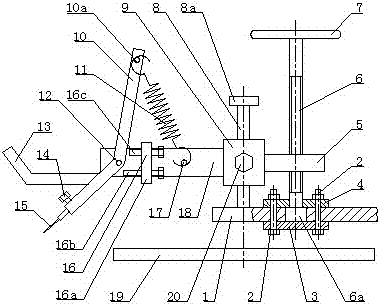
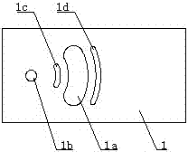
[0008] see Figure 1 to Figure 2 , the present invention includes a cloth pressing handle 15 and a circular dial 19, and also includes a frame 1, two bolts 2, a lower pressing plate 3, an upper pressing plate 4, a connecting plate 5, a screw rod 6, a hand wheel 7, a sliding rod 8, a sliding Seat 9, fork 10, tension spring 11, rotating shaft 12, operating rod 13, pressure cloth handle compression screw 14, limit device 16, seat board pin 17, seat board 18 and sliding seat locking screw 20, described The limit device 16 comprises a limit seat 16a, a lower limit screw 16b and an upper limit screw 16c, the limit seat 16a is welded on the seat plate 18, and the upper limit screw 16c and the lower limit screw 16b are respectively assembled by threaded connections. At the upper and lower parts of the limit seat 16a, the frame 1 is provided with a large waist-shaped hole 1a, a slide rod hole 1b, a short waist-shaped hole 1c and a long waist-shaped hole 1d, and the lower end of the scr...


PUM


Abstract

The invention discloses an oscillating rod type cloth-pressing handle which comprises a cloth-pressing handle and a round needle disk, and is characterized by further comprising a machine frame, two bolts, a lower pressing plate, an upper pressing plate, a connecting plate, a screw rod, a hand wheel, a sliding rod, a sliding base, an oscillating rod, an extension spring, a rotating shaft, an operating rod, a cloth-pressing handle pressing screw, a limiting device, a seat plate pin, a seat plate and a sliding seat locking screw, wherein the limiting device comprises a limiting seat, a lower limiting screw and an upper limiting screw; the limiting seat is welded on the seat plate; the upper limiting screw and the lower limiting screw are connected and arranged to the upper part and the lower part of the limiting seat respectively through threads; the machine frame is provided with a big waist-shaped hole, a sliding rod hole, a short waist-shaped hole and a long waist-shaped hole; a limiting block is arranged at the lower end of the screw rod. The oscillating rod type cloth-pressing handle is novel in structure, labor-saving in operation, high in production efficiency, excellent in pressing effect and long in service life.

Description

technical field [0001] The invention relates to a textile machine, in particular to a swing rod type cloth pressing handle. Background technique [0002] Most of the knitted garments are finished by weaving in pieces and then sewing them on the sewing machine. When sewing, the two pieces of textiles are combined first and then inserted into the teeth of the circular dial of the sewing machine, and then the operator presses The cloth handle presses the two pieces of textiles tightly to make them fit each other, and then sews them up. Most of the existing cloth pressing handles are made of a fixed structure, and the width of the toothed part is small. Such a structure is more suitable for sewing. When knitwear with a large seam surface needs to be pressed in multiple times, the labor intensity of the workers is relatively high, and the production efficiency is low. Contents of the invention [0003] The object of the present invention is to provide a swing rod type cloth pr...

Claims


Application Information

Patent Timeline
Patent Type & Authority Patents(China)
IPC IPC(8): D04B39/08
Inventor 黄凌志
Owner DAYE XINGYUN ELECTROMECHANICAL TECH RES INST
Why Eureka
Try Eureka