Self-induction Magneto-rheological Damping Pipe Clamp

A vibration damping tube and magneto-rheological technology, applied in the direction of shock absorbers, shock absorbers, pipe supports, etc., can solve problems such as inconvenient installation and fixing of pipelines, failure to ensure system stability, and pipelines affecting system safety, etc., to achieve Improve pipeline life and reliability, simple and convenient operation, and reduce pipeline vibration

Active Publication Date: 2017-01-18
YANSHAN UNIV
View PDF8 Cites 8 Cited by
  • Summary
  • Abstract
  • Description
  • Claims
  • Application Information

AI Technical Summary

Problems solved by technology

However, it does not substantially weaken the pipeline vibration, and the vibration of the pipeline still affects the safety of the system
[0005] The Chinese invention patent with the notification number CN103104646B discloses a clamp-type damper for controlling the multi-dimensional vibration of a tubular structure. Axial and circumferential damping springs, rubber damping rings and anti-collision pads are respectively arranged outside the tubular structure, which can reduce the The axial and circular vibrations of the tubular structure, but the structure is complex, and it is inconvenient to install and fix the pipeline, which cannot guarantee the stability of the system. Damage to the road system, resulting in safety accidents

Method used


Image

  • Self-induction Magneto-rheological Damping Pipe Clamp
  • Self-induction Magneto-rheological Damping Pipe Clamp
  • Self-induction Magneto-rheological Damping Pipe Clamp

Examples


Embodiment Construction

[0022] specific implementation plan

[0023] The present invention will be further described below in conjunction with the accompanying drawings and embodiments.

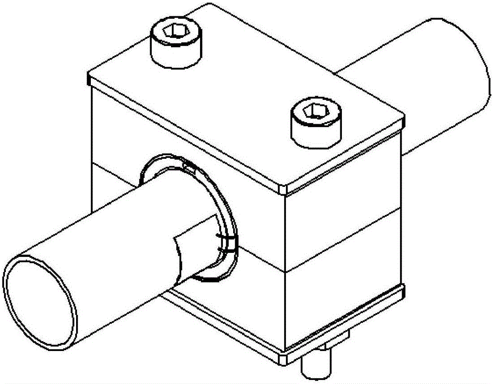
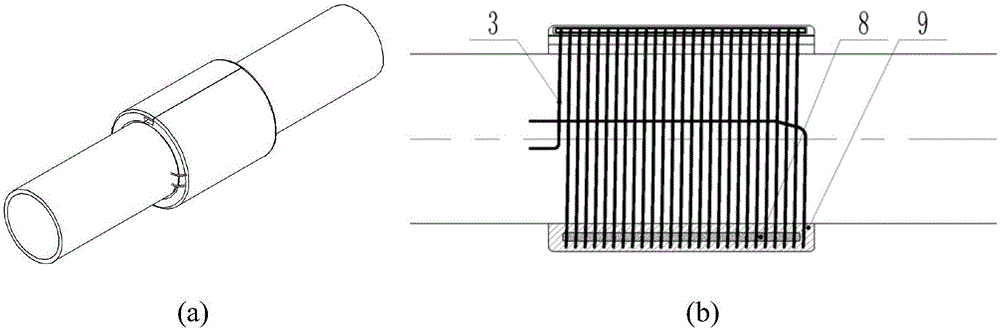
[0024] Such as Figure 1~2 As shown, a self-induction magneto-rheological damping pipe clip of the embodiment of the present invention has a damping rubber sleeve 9 on the outside of the pipeline 1, and a magneto-rheological fluid material 8 and a metal coil are inside the vibration-damping rubber sleeve. 3. Both ends of the metal coil wire are connected to a MEMS vibrating micro-energy device 2 attached to the outer wall of the pipeline. The upper and lower pipe clamps 4 and 10 are fastened to the vibration-damping rubber sleeve, and the upper and lower pipe clamps pass through The fixed top cover 5 and the fixed bottom plate 11 are fixed by two pairs of hexagon socket bolts 6 and nuts 7 . There are anti-slip depressions in the upper and lower pipe clamps (see figure 2 ), this design can not only ensure the cla...


PUM


Abstract

The invention discloses a self-induction magneto-rheological damping pipe clamp, which comprises a fixed top cover, a vertical pipe clamp, a damping rubber sleeve, a micro energy conversion unit and a fixed bottom plate. The rubber cavity of the damping rubber sleeve is filled with a magnetic rheological fluid material. The micro energy conversion unit arranges the metal coil in the damping rubber sleeve, and is wound on the outside of the magneto-rheological fluid material. Two ends of the coil are electrically connected with the MEMS vibrating electromagnetic micro power device, and when the pipeline vibrates, the MEMS vibrating electromagnetic micro power device absorbs the vibration energy of the pipeline and converts it into electric energy so as to generate a magnetic field after the coil is energized, and the magnetic rheological fluid material is cured under the action of the magnetic field, and the curing degree increases with the strength of the magnetic field, thereby changing the rigidity of the damping rubber sleeve, increasing the clamping degree to the pipeline, and finally reducing the vibration of the pipeline. In this invention, the vibration absorption vibration of the pipeline can be realized, the rigidity and clamping degree of the pipe clamp can be regulated according to the vibration degree of the pipeline, and the absorption and reuse of the vibration energy can be realized.

Description

technical field [0001] The invention belongs to the field of mechanical engineering and relates to the fixing and vibration reduction of pipelines, in particular to a self-induction magneto-rheological vibration damping pipe clamp, which is especially suitable for fixing and vibration reduction of aviation hydraulic pipelines. Background technique [0002] Pipe clamps are an indispensable component for pipe fixing and connection. It is necessary to ensure sufficient connection strength and ensure the tightness of pipe connections. The vibration effect of the existing pipe clamp is poor, and strong vibration will damage the pipeline or even cause it to break, thereby affecting the safety of the entire system. [0003] The rapid development of modern aerospace drives the development of aircraft towards large-scale and high-speed. The number of aviation pipelines of a single aircraft has also increased significantly, the aircraft pipeline system is more complex, and the space ...

Claims


Application Information

Patent Timeline
Patent Type & Authority Applications(China)
IPC IPC(8): F16L3/10F16L3/205F16L3/215F16F15/027F16F15/03F16F15/08F16F9/53
CPCF16F9/535F16F15/022F16F15/027F16F15/03F16F15/08F16F2224/045F16L3/1091F16L3/205F16L3/215
Inventor 权凌霄李斌郭猛
Owner YANSHAN UNIV
Why Eureka
Try Eureka