Air conditioner heat recycling system

A heat recovery and air-conditioning technology, applied in air-conditioning systems, space heating and ventilation, space heating and ventilation details, etc., can solve the problems that the refrigerant cannot flow through, and the heat dissipation of the drive cooling module 7 cannot be realized.

Active Publication Date: 2017-01-18
GREE ELECTRIC APPLIANCES INC
View PDF6 Cites 15 Cited by
  • Summary
  • Abstract
  • Description
  • Claims
  • Application Information

AI Technical Summary

Problems solved by technology

[0004] When the air-conditioning heat recovery system is in the complete heat recovery mode, the indoor unit 1 has cooling and heating modes at the same time, and the sum of the heating capacity of the indoor unit 1 in the heating mode is basically equal to the sum of the cooling capacity of the indoor unit 1 in the cooling mode. At this time, there is no need for the heat exchanger 8 o

Method used


Image

  • Air conditioner heat recycling system
  • Air conditioner heat recycling system
  • Air conditioner heat recycling system

Examples


Embodiment 1

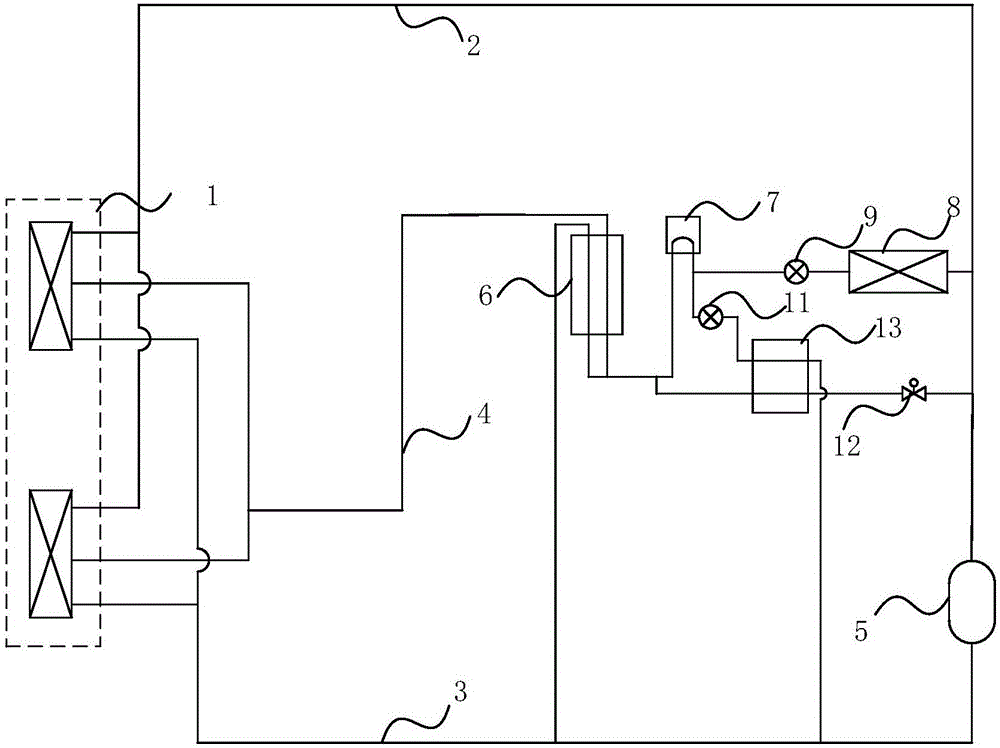
[0022] figure 2 It is a schematic structural diagram of an air-conditioning heat recovery system provided in Embodiment 1 of the present invention. The system includes an internal unit 1, a high-pressure air pipe 2, a low-pressure air pipe 3, a liquid pipe 4, a compressor 5, a subcooler 6, and a drive heat dissipation module 7 , Outdoor unit heat exchanger 8, first electric control valve 11, second electric control valve 12 and heat exchanger 13.

[0023] Among them, the first electronically controlled valve 11 is connected in series between the liquid outlet pipe of the driving heat dissipation module 7 and the low-pressure air pipe 3 to form a first pipeline; the second electronically controlled valve 12 is connected in series between the liquid inlet pipe and the high-pressure air pipe of the driving heat dissipation module 7 2, forming a second pipeline; the heat exchanger 13 respectively connects the first pipeline and the second pipeline, and transfers the heat of the h...

Embodiment 2

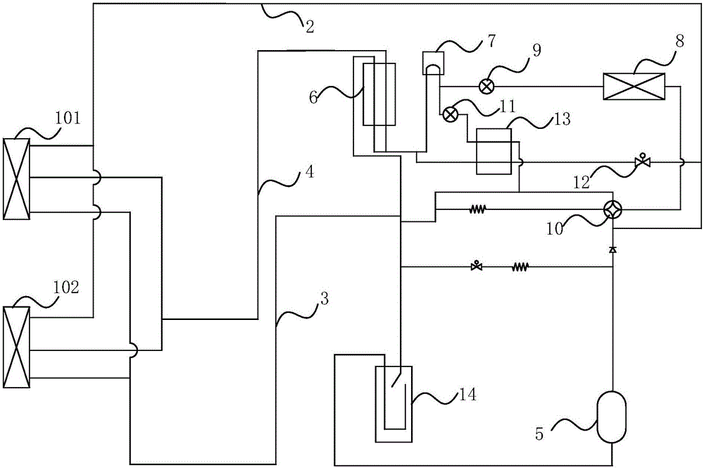
[0035] image 3 It is a schematic structural diagram of an air-conditioning heat recovery system provided in Embodiment 2 of the present invention. The system includes an indoor unit, a high-pressure air pipe 2, a low-pressure air pipe 3, a liquid pipe 4, a compressor 5, a subcooler 6, a drive cooling module 7, an outdoor unit heat exchanger 8, a heating electronic expansion valve 9, and a four-way valve 10 , the first electric control valve 11, the second electric control valve 12, the heat exchanger 13 and the gas-liquid separator 14. Wherein, the internal machine is connected with the high-pressure air pipe 2, the low-pressure air pipe 3 and the liquid pipe 4. The low-pressure air pipe 3 is connected to the air inlet of the compressor 5 , the high-pressure air pipe 2 is connected to the air outlet of the compressor 5 , and a gas-liquid separator 14 is connected in series between the internal machine and the compressor 5 . The compressor 5 compresses the refrigerant flowin...


PUM


Abstract

The embodiment of the invention discloses an air conditioner heat recycling system which comprises electric control valves and a heat exchanger. At least one electric control valve is connected between a liquid outlet pipe of a heat dissipation driving module and a low-pressure air pipe in series, and a first pipeline is formed. At least one electric control valve is connected between a liquid inlet pipe of the heat dissipation driving module and a high-pressure air pipe in series, and a second pipeline is formed. The heat exchanger is connected with the first pipeline and the second pipeline, so that heat of a high-temperature refrigerant in the second pipeline is transferred to a low-temperature refrigerant in the first pipeline. According to the air conditioner heat recycling system, under the complete heat recycling mode, heat dissipation of the heat dissipation driving module can be achieved, the situation that the system is damaged due to excessively high temperature of the heat dissipation driving module is avoided, and the working stability and safety of the air conditioner heat recycling system are improved.

Description

technical field [0001] Embodiments of the present invention relate to the technical field of household appliances, and in particular to an air conditioner heat recovery system. Background technique [0002] Such as figure 1 As shown, the current air-conditioning heat recovery system generally includes indoor unit 1, high-pressure air pipe 2, low-pressure air pipe 3, liquid pipe 4, compressor 5, subcooler 6, drive cooling module 7, outdoor unit heat exchanger 8, and indoor unit 1 Connect the high-pressure air pipe 2, low-pressure air pipe 3 and liquid pipe 4, the low-pressure air pipe 3 is connected to the air inlet of the compressor 5, the high-pressure air pipe 2 is connected to the air outlet of the compressor 5, and the compressor 5 compresses the refrigerant flowing through the low-pressure air pipe 3 into high pressure The high-temperature gaseous refrigerant enters the high-pressure gas pipe 2, the liquid pipe 4 is connected to the subcooler 6 and the driving heat dis...

Claims


Application Information

Patent Timeline
IPC IPC(8): F24F3/06F25B41/04F24F13/30F25B41/00F25B41/06F25B41/20F25B41/34F25B41/40
CPCF24F3/065F24F13/30F25B41/00F25B41/20F25B41/345Y02B30/70
Inventor 罗亚军张仕强武连发贾翔
Owner GREE ELECTRIC APPLIANCES INC
Why Eureka
Try Eureka