Shooting lens and camera device assembled with shooting lens

A camera lens and lens technology, applied in optical components, optics, instruments, etc., can solve problems such as unfavorable processing, inability to meet miniaturization and light weight, and long lens size, and achieve the effect of being beneficial to production and processing.

Active Publication Date: 2017-01-18
ZHEJIANG SUNNY OPTICAL CO LTD
View PDF6 Cites 30 Cited by
  • Summary
  • Abstract
  • Description
  • Claims
  • Application Information

AI Technical Summary

Problems solved by technology

[0003] Usually, in order to meet the requirements of high pixels, conventional camera lenses usually adopt a large-aperture configuration, resulting in a relatively long lens size, and it will be difficult to match high-pixel photosensitive chips
At the same time, in order to meet the high imaging quality, there is a certain limitation on increasing the field of view, which is usually overcome by increasing the number of lenses, but this c

Method used


Image

  • Shooting lens and camera device assembled with shooting lens
  • Shooting lens and camera device assembled with shooting lens
  • Shooting lens and camera device assembled with shooting lens

Examples


Example Embodiment

[0106] Example 1

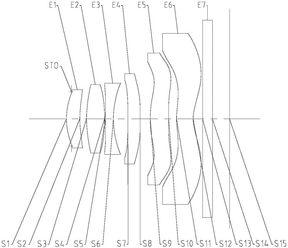
[0107] Refer to the following Figure 1 to Figure 2D Example 1 of the imaging lens of the above-described embodiment of the present application will be described.

[0108] like figure 1 As shown, Embodiment 1 of the imaging lens includes a first lens E1 having an object side S1 and an image side S2, a second lens E2 having an object side S3 and an image side S4, and a third lens having an object side S5 and an image side S6 E3, fourth lens E4 with object side S7 and image side S8, fifth lens E5 with object side S9 and image side S10, and sixth lens E6 with object side S11 and image side S12. The imaging lens may further include a diaphragm (not shown) and a filter E7 having an object side surface S13 and an image side surface S14 for filtering out infrared light. In the imaging lens of this embodiment, an aperture STO may also be provided to adjust the amount of incoming light. The light from the object passes through each of the surfaces S1 to S14 in ...

Example Embodiment

[0124] Example 2

[0125] Refer to the following Figures 3 to 4D Embodiment 2 of the above-described imaging lens of the present application will be described. In addition to the parameters of each lens of the imaging lens, for example, in addition to the curvature radius, thickness, material, conic coefficient, effective focal length, on-axis distance, high-order coefficient of each mirror surface of each lens, etc. The image pickup lens described in the following embodiments is the same as the image pickup lens described in Embodiment 1 in the same arrangement. For the sake of brevity, some descriptions similar to those of Embodiment 1 will be omitted.

[0126] image 3 A schematic structural diagram of the imaging lens according to Embodiment 2 of the present application is shown. like image 3 As shown, the imaging lens according to Embodiment 2 includes first to sixth lenses E1 to E6 having an object side surface and an image side surface, respectively.

[0127] ...

Example Embodiment

[0141] Example 3

[0142] Refer to the following Figures 5 to 6D Embodiment 3 of the imaging lens of the present application will be described. Figure 5 A schematic structural diagram of the imaging lens according to Embodiment 3 is shown. like Figure 5 As shown, the imaging lens according to Embodiment 3 includes first to sixth lenses E1 to E6 having an object side surface and an image side surface, respectively. Table 7 below shows the effective focal lengths f1-f6 of each lens in Example 3, the total effective focal length f of the imaging lens, the total length TTL of the imaging lens, and the half field of view (diagonal) angle HFOV.

[0143] f1(mm) 13.83 f(mm) 3.49 f2(mm) 2.91 TTL(mm) 4.31 f3(mm -4.94 HFOV(deg) 37.51 f4(mm) -117.27 f5(mm) 5.92 f6(mm) -4.47

[0144] Table 7

[0145] In Embodiment 3, the effective focal length f1 of the first lens E1 and the total effective focal length f satisfy: ...


PUM


Abstract

The invention discloses a shooting lens and a camera device assembled with the shooting lens. The shooting lens comprises a first lens, a second lens, a third lens and multiple subsequent lenses; the first lens, the second lens, the third lens and the multiple subsequent lenses are arranged from the object side to the image side successively along the optical axis, and form a total effective focal length f; and the shooting lens is characterized in that a combined focal length f12 of the first and second lenses and a focal length f3 of the third lens satisfy that -0.7<f12/f3<0.

Description

technical field [0001] The present application relates to a camera lens and a camera device equipped with the camera lens. Background technique [0002] In recent years, with the improvement of semiconductor manufacturing technology, the pixel size of the photosensitive element has been continuously reduced. Correspondingly, the camera lens mounted on electronic products such as mobile phones and digital cameras has gradually developed towards the field of miniaturization and high pixel. [0003] Usually, in order to meet the requirements of high pixels, conventional camera lenses usually adopt a large-aperture configuration, resulting in a relatively long lens size, which makes it difficult to match high-pixel photosensitive chips. At the same time, in order to meet the high imaging quality, there is a certain limitation on increasing the field of view, which is usually overcome by increasing the number of lenses, but this cannot meet the requirements of miniaturization and...

Claims


Application Information

Patent Timeline
IPC IPC(8): G02B13/00
CPCG02B13/0015G02B13/0045G02B9/62
Inventor 闻人建科黄林吕赛锋
Owner ZHEJIANG SUNNY OPTICAL CO LTD
Why Eureka
Try Eureka