Eureka AIR delivers breakthrough ideas for toughest innovation challenges, trusted by R&D personnel around the world.

Bayonet connector, its mfg. method, electronic insertion sheet and electronic appliance

A card edge connector, electronic equipment technology, applied in the direction of connection, printed circuit manufacturing, two-component connection device, etc., can solve the problems of complicated manufacturing work and increased cost.

Inactive Publication Date: 2006-10-04
FUJITSU LTD
View PDF0 Cites 2 Cited by
  • Summary
  • Abstract
  • Description
  • Claims
  • Application Information

AI Technical Summary

Problems solved by technology

However, in the case of this card edge connector, many steps are required in the manufacturing process, the manufacturing work becomes very complicated, and the cost is inevitably increased.

Method used


Image

  • Bayonet connector, its mfg. method, electronic insertion sheet and electronic appliance
  • Bayonet connector, its mfg. method, electronic insertion sheet and electronic appliance
  • Bayonet connector, its mfg. method, electronic insertion sheet and electronic appliance

Examples


Embodiment Construction

[0035] As mentioned above, the present invention provides a card edge connector for electrical connection and its manufacturing method, and an electronic blade and electronic equipment including the card edge connector of the present invention.

[0036] The card edge connector of the present invention is used for inserting and installing an electronic card such as a memory card in a connector provided on a substrate such as a motherboard of a semiconductor device, so as to establish an electrical connection between the electronic card and the semiconductor device, so that The electronic insert has electronic devices such as LSI chips packaged thereon.

[0037] In this specification, the term "electronic device" refers to various devices generally mounted on semiconductor equipment, and specifically, includes semiconductor devices such as IC chips and LSI chips, capacitors, transformers, choke coils, printed boards, and the like. In a broad sense, electronic devices also includ...


PUM


Abstract

A card edge connector comprises a connector body and a conductive pad, and is constructed such that the conductive pad terminates at a predetermined distance from the end of the tip portion of the connector body, and that there is further provided a protective pad, adjacent to the terminating portion of the conductive pad, which is formed at the same time with the formation of a wiring pattern in a post-fabrication step of the wiring pattern. Using the card edge connector, an electric card and an electric equipment are also provided.

Description

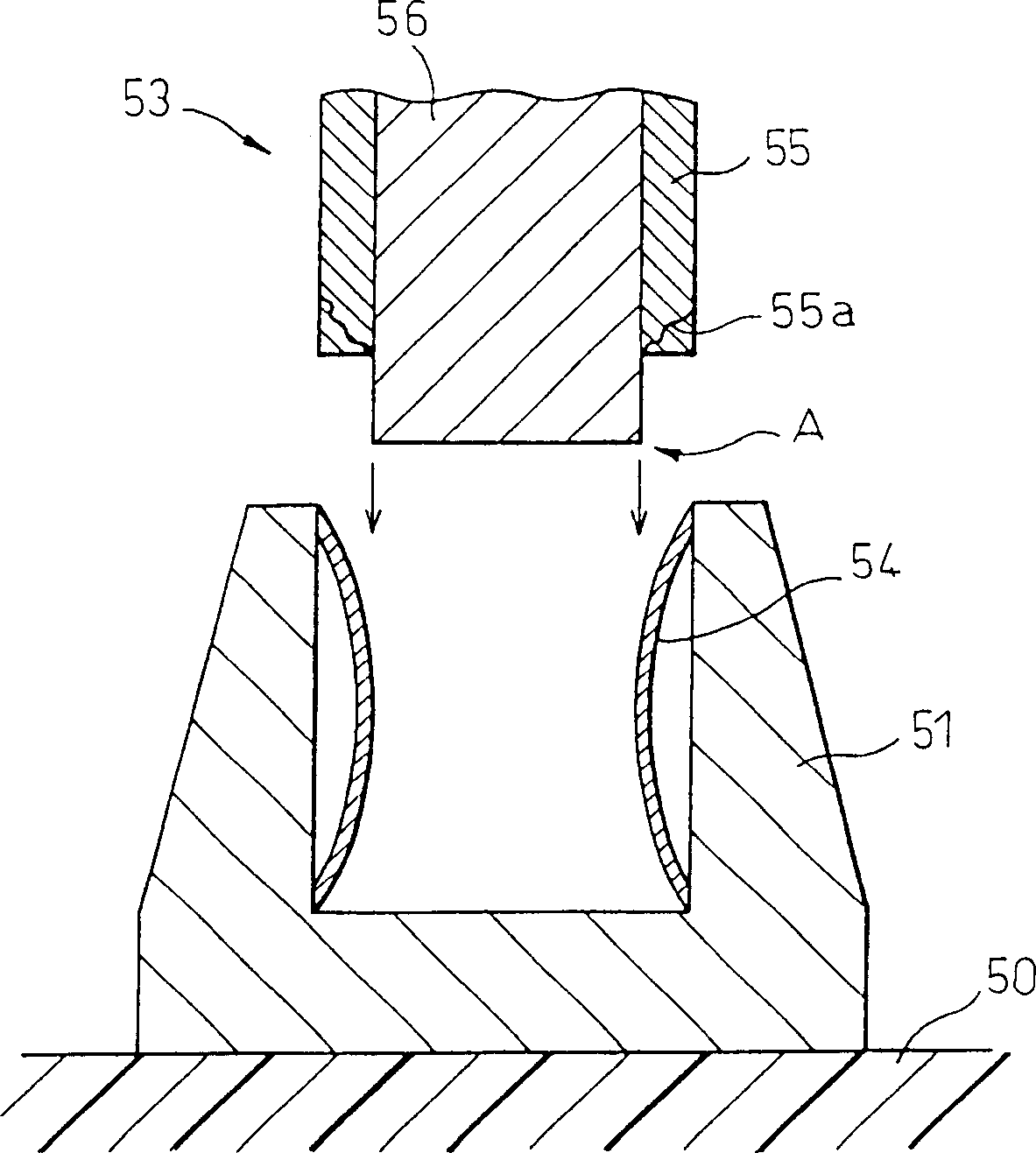
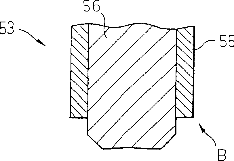
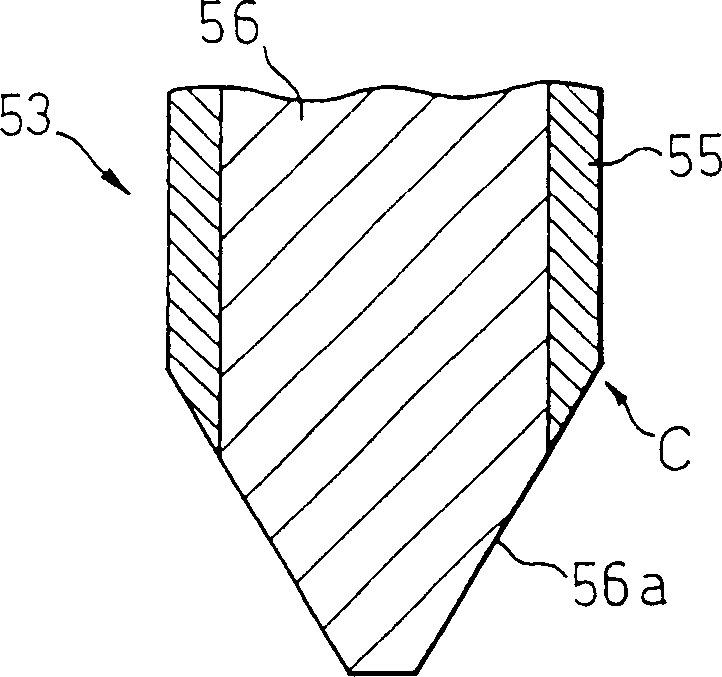
technical field [0001] The present invention relates to card edge connectors, and more particularly, to card edge connectors for inserting and installing electronic inserts packaged with electronic devices in connectors of electronic equipment, and to electronic inserts and use of card edges Connectors for electronic devices. Background technique [0002] It is well known in the art that when a card-like printed circuit is to be implemented in an electronic device, the general approach is to provide a card edge connector at the end of the printed circuit board, insert the card edge connector and assemble it on the edge of the electronic device. in the connector. [0003] FIG. 1 is a sectional view showing an example of a prior art card edge connector and its use. In the illustrated example, the adopted structure is that the electronic device 50 is provided with a connector 51 having a socket structure, and a card edge connector 53 as a plug is directly inserted into the co...

Claims


Application Information

Patent Timeline
Patent Type & Authority Patents(China)
IPC IPC(8): H01R24/00H05K1/11H05K3/00G06K19/067H01R43/00H05K1/02H05K3/28H05K3/34
CPCH05K2201/098H05K2201/09909H01R12/714H05K2203/0594H05K1/117H01R12/721H05K2201/10863H05K3/3452H05K2201/09154
Inventor 江口进岛森浩
Owner FUJITSU LTD
Why Eureka
Eureka Blog
Learn More