
Coil component and manufacturing method thereof

A technology of coil components and manufacturing methods, which is applied in coil manufacturing, transformer/inductor components, inductor/transformer/magnet manufacturing, etc. Effect

Active Publication Date: 2017-01-18
TDK CORPARATION
View PDF14 Cites 6 Cited by
  • Summary
  • Abstract
  • Description
  • Claims
  • Application Information

AI Technical Summary

Problems solved by technology

However, according to studies by the inventors of the present invention, it has been found that when the movement of the covered wire is significant, the insulation withstand voltage is slightly lowered compared to the case where this is not the case.

Method used


Image

  • Coil component and manufacturing method thereof
  • Coil component and manufacturing method thereof
  • Coil component and manufacturing method thereof

Examples


Embodiment

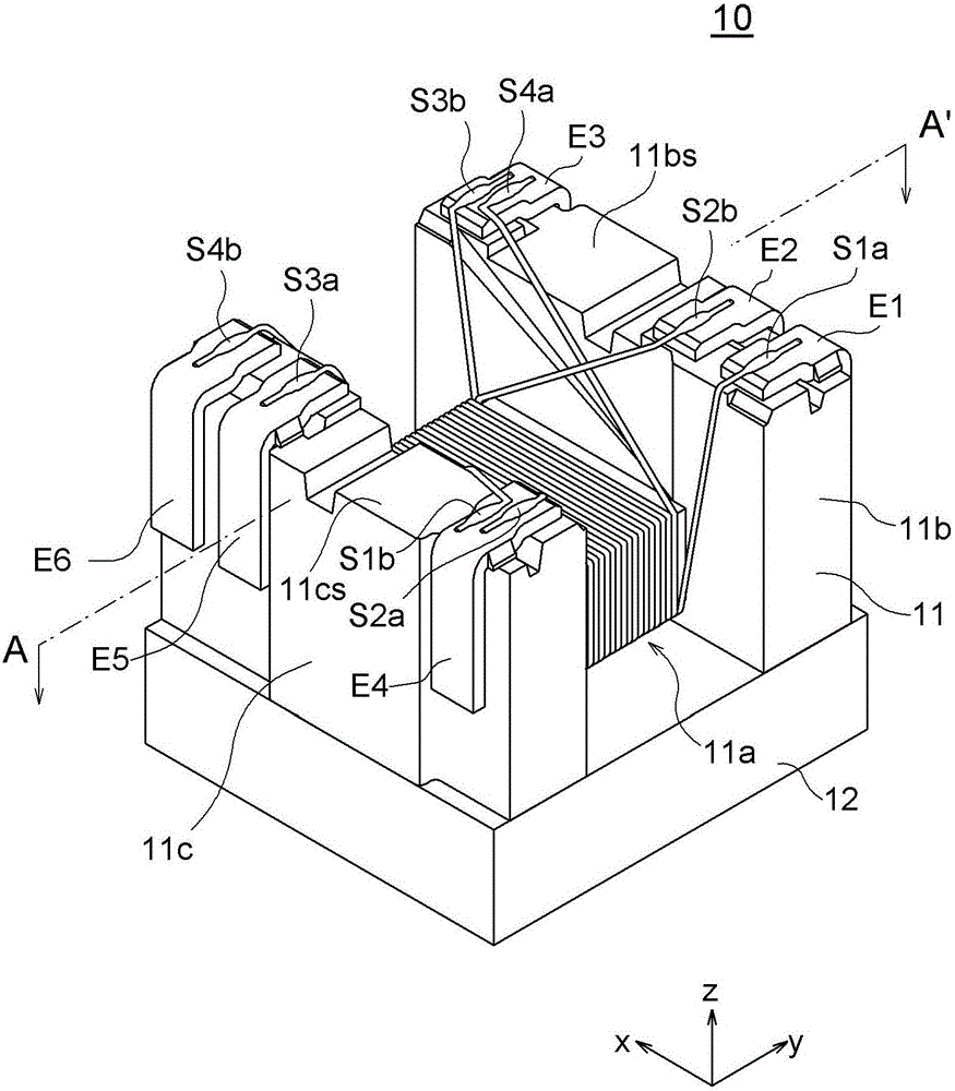
[0115] ready to have figure 1 A drum core 11 having a shape as shown, a length in the x direction of 4.5 mm, a width in the y direction of 3.2 mm, and a height in the z direction of 2.9 mm. also ready to have Image 6In the cross section shown, the core material 31 has a diameter of 40 μm, the film thickness of the coating film 32 is 10 μm, and the film thickness of the resin film 33 is 1 μm or 3.5 μm. Wound around the drum core 11. However, the formation of the connection portions E1 to E6 is omitted, and both ends of the covered conductive wires S1 to S4 are left open. Let the samples using the coated conductive wires S1 to S4 with the resin film 33 having a film thickness of 1 μm be referred to as “Sample A”, and the samples using the coated conductive wires S1 to S4 with the resin film 33 having a film thickness of 3.5 μm be referred to as “Sample A”. B".

[0116] Next, the resin film 33 is melted by applying a heat load, and then cooled to form the resin coating layer...


PUM

PropertyMeasurementUnit
melting pointaaaaaaaaaa

Abstract

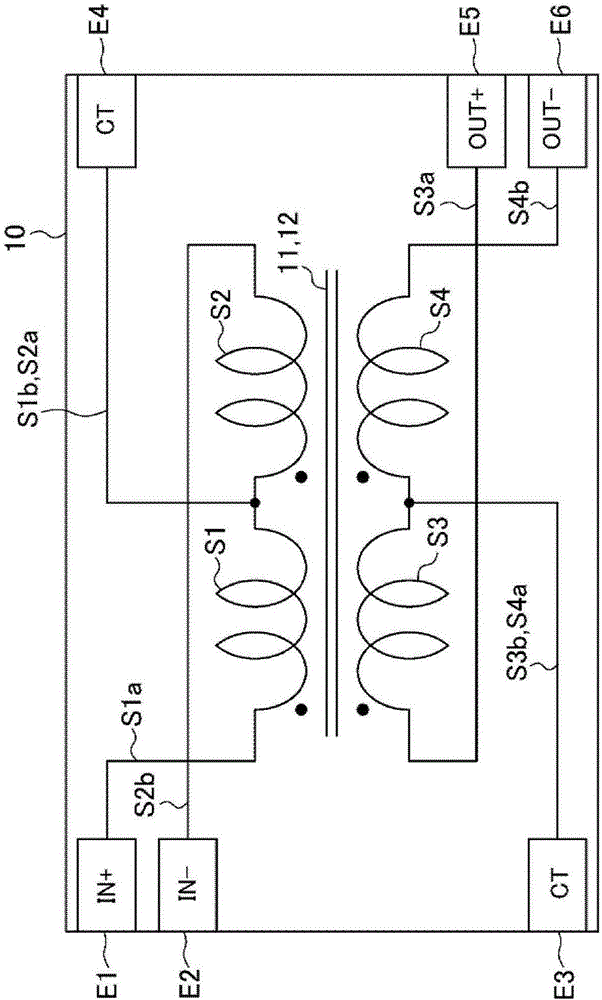
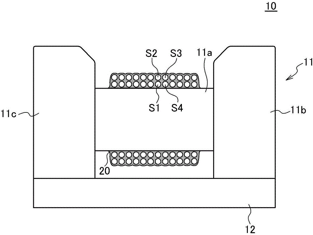
The invention discloses a coil component and a manufacturing method thereof. The coil component includes: a plurality of coated conductive wires (S1, S4) forming a first winding layer wound around a winding core portion and a second winding layer wound around the winding core portion; and a resin coating layer (20) covering the coated conductive wires (S1, S4). A maximum space (W1) between the coated conductive wires (S1, S4) in the first winding layer is narrower than a diameter (as shown in the description) of the coated conductive wires. Therefore, the coil component can ensure higher isolation voltage.

Description

technical field [0001] The present invention relates to a coil component and its manufacturing method, and particularly to a coil component using a drum core and its manufacturing method. Background technique [0002] In recent years, electronic components used in information terminals such as smartphones have been strongly required to be smaller and thinner. Therefore, coil components such as pulse transformers do not use toroidal cores, but surface mount coil components using drum cores are widely used. For example, Patent Document 1 discloses a surface mount type step-up transformer using a drum core. [0003] Coil components using drum cores are also required to be further downsized and thinned. Therefore, the size of the winding core is reduced every year, and in order to secure the required inductance, it is necessary to use a coated wire with a smaller wire diameter. [0004] prior art literature [0005] patent documents [0006] Patent Document 1: Japanese Pate...

Claims


Application Information

Patent Timeline
Patent Type & Authority Applications(China)
IPC IPC(8): H01F17/04H01F27/32H01F41/12
CPCH01F17/045H01F27/324H01F41/125H01F27/2828H01F27/292H01F27/327H01F41/127H01F41/069
Inventor 御子神祐高木信雄大井康裕芦泽瞬土田节
Owner TDK CORPARATION
Learn More