A Safe and Labor-saving Bending and Forming Structure for Cables of Distribution Lines

A technology of distribution lines and pull wires, which is applied in the direction of overhead lines/cable equipment, etc., can solve the problems of personal injury of operators, low work efficiency, and large rebound force of pull wires, etc., to improve safety and reliability, and to achieve good connection reliability , the effect of reducing labor intensity

Active Publication Date: 2018-01-19
SHANGHE COUNTY POWER SUPPLY CO STATE GRID SHANDONG ELECTRIC POWER CO +1
View PDF6 Cites 0 Cited by
  • Summary
  • Abstract
  • Description
  • Claims
  • Application Information

AI Technical Summary

Problems solved by technology

[0002] In the prior art, the wire bending equipment such as utility poles usually adopts manual bending and hand-held tools for bending. The defects of this bending method and structure are that the labor intensity of the operator is high, the work efficiency is low, and the bending and forming Poor accuracy and poor matching between the connected parts during installation and use will easily cause uneven force on the contact parts, affect subsequent use, local degeneration and damage, and even affect the safety of the person, gasket, circuit and equipment used. Since the pull wire has a large rebound force after being bent, it is unsafe to rebound easily and cause personal injury to the operator during operation.

Method used


Image

  • A Safe and Labor-saving Bending and Forming Structure for Cables of Distribution Lines
  • A Safe and Labor-saving Bending and Forming Structure for Cables of Distribution Lines
  • A Safe and Labor-saving Bending and Forming Structure for Cables of Distribution Lines

Examples


Embodiment Construction

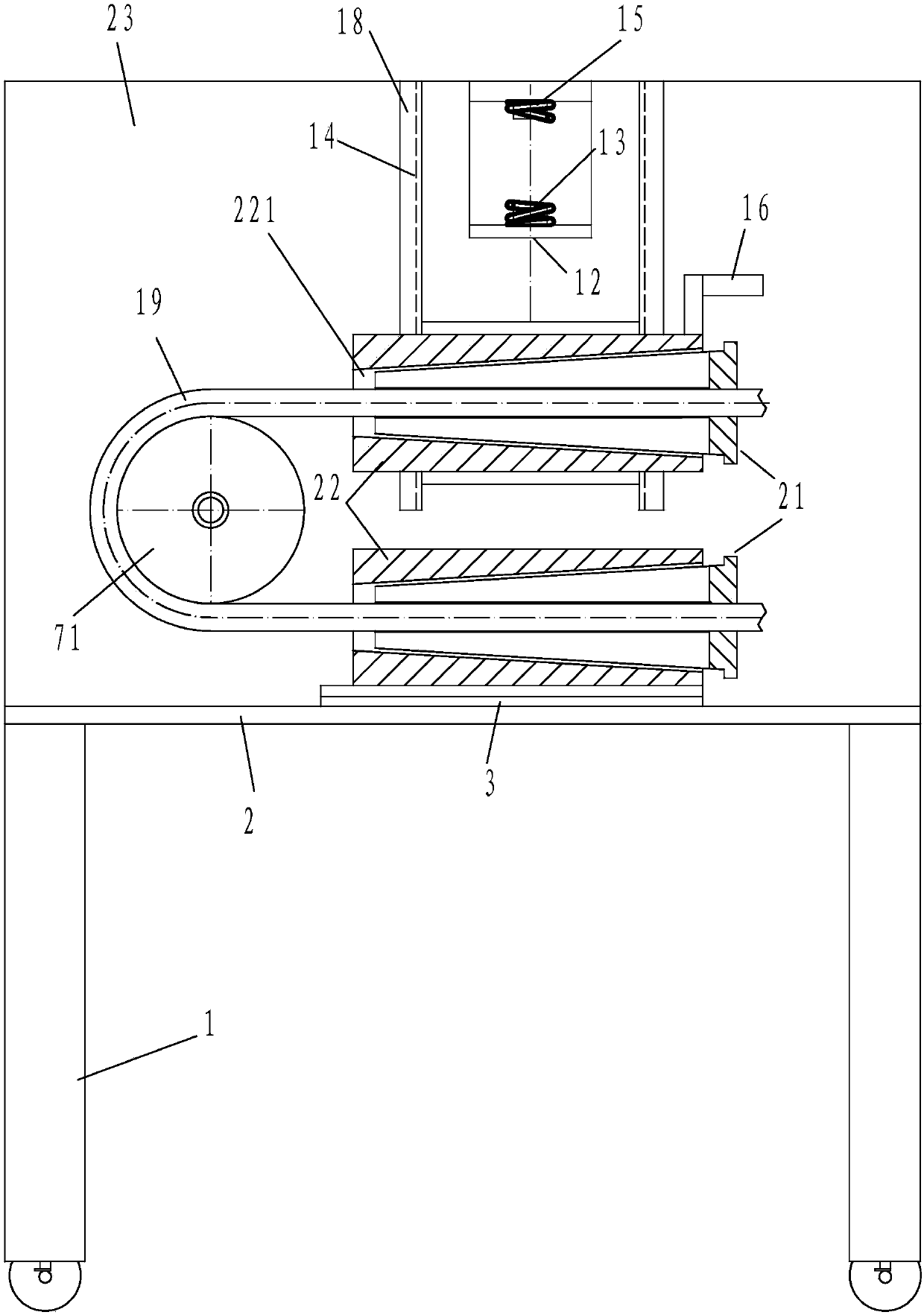
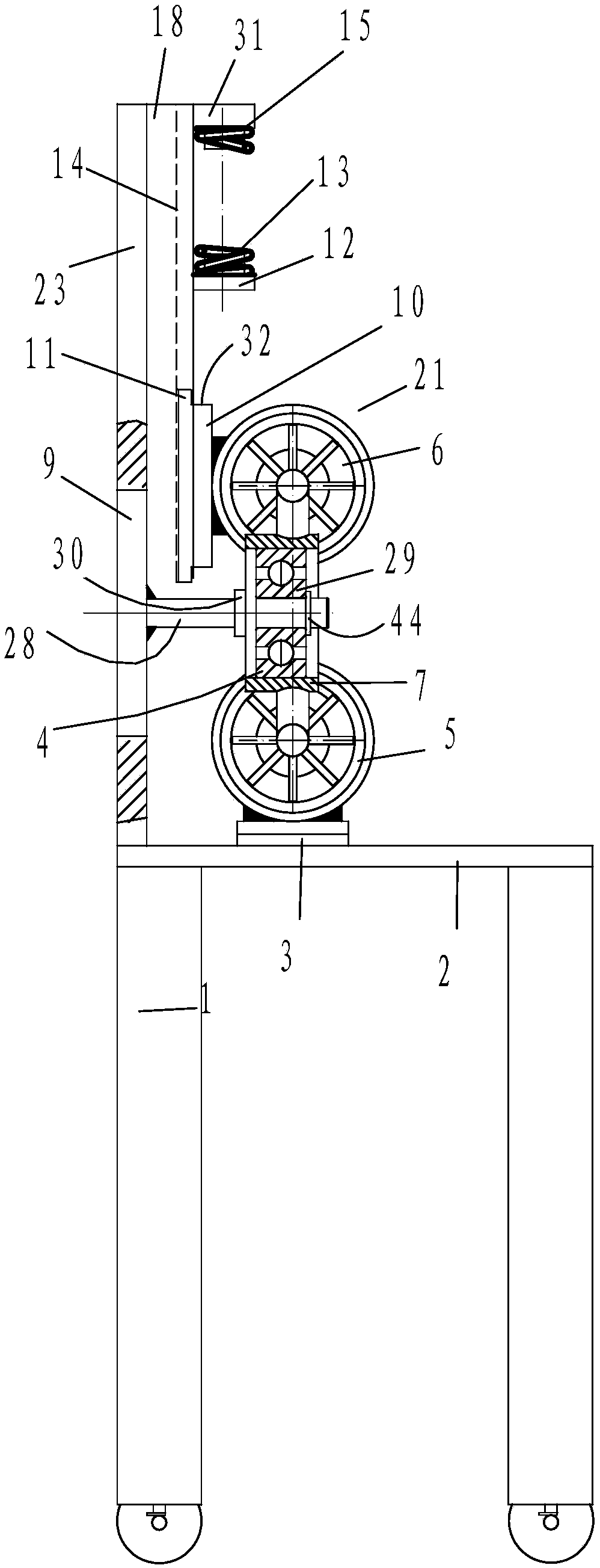
[0030] In order to better understand the present invention, the implementation manner of the present invention will be explained in detail below in conjunction with the accompanying drawings.

[0031] Such as Figure 1 to Figure 4 As shown, a safe and labor-saving cable bending and forming structure for distribution lines includes vertical support 1 and horizontal support 2 connected to each other. The horizontal support 2 is provided with a support structure under the cable, and the vertical support 1 is provided with The support structure on the stay wire and the bending and positioning structure of the stay wire, the bending and positioning structure of the stay wire includes a fixed shaft 7, on which a stay wire positioning sleeve 71 that can rotate around the fixed shaft is arranged, and one end of the stay wire 30 is connected to the bottom of the stay wire The supporting structure cooperates, and the other end of the stay wire is matched with the supporting structure on...


PUM


Abstract

The invention discloses a safe and labor-saving distribution line stay wire bending formation structure. The structure comprises vertical supports and a horizontal support, wherein the horizontal support is provided with a stay wire upper holding structure, the vertical supports are provided with a stay wire upper holding structure and a stay wire bending positioning structure, the stay wire bending positioning structure comprises a fixation shaft and a stay wire positioning sleeve, the two ends of a stay wire respectively cooperate with the stay wire lower holding structure and the stay wire upper holding structure, the stay wire upper holding structure is connected with a slide block, the vertical supports are provided with vertical guide rails, and the slide block cooperates with grooves in the vertical guide rails; the stay wire lower holding structure, the stay wire upper holding structure each comprise a fixation sleeve and a hollow shaft, the fixation sleeves are provided with conical holes, the hollow shafts are provided with outer conical surfaces and inner cylindrical holes, and the hollow shafts are provided with multiple opening grooves which are open along axial small ends on cones; the outer conical surfaces of the hollow shafts and the small ends of the conical holes are close to the stay wire bending positioning structure; and a lower stay wire compression structure and an upper stay wire compression structure are arranged between the stay wire lower holding structure and the stay wire bending positioning structure.

Description

technical field [0001] The invention relates to the technical field of cable bending processing equipment, in particular to a safe and labor-saving cable bending and forming structure for distribution lines. Background technique [0002] In the prior art, the wire bending equipment such as utility poles usually adopts manual bending and hand-held tools for bending. The defects of this bending method and structure are that the labor intensity of the operator is high, the work efficiency is low, and the bending and forming Poor accuracy and poor matching between the connected parts during installation and use will easily cause uneven force on the contact parts, affect subsequent use, local degeneration and damage, and even affect the safety of the person, gasket, circuit and equipment used. Since the backguy has a relatively large rebound force after being bent, it is unsafe to rebound easily and cause injury to the operator during operation. Contents of the invention [00...

Claims


Application Information

Patent Timeline
Patent Type & Authority Patents(China)
IPC IPC(8): H02G1/02
CPCH02G1/02
Inventor 刘学瑞芮吉国
Owner SHANGHE COUNTY POWER SUPPLY CO STATE GRID SHANDONG ELECTRIC POWER CO
Why Eureka
Try Eureka