
Electric automobile DC charging pile heat dissipation apparatus and method

A technology for DC charging piles and electric vehicles, which is applied to the modification of power electronics, electrical components, and structural parts of electrical equipment. The effect of cooling effect

Active Publication Date: 2017-01-18
特变电工南京智能电气有限公司
View PDF10 Cites 5 Cited by
  • Summary
  • Abstract
  • Description
  • Claims
  • Application Information

AI Technical Summary

Problems solved by technology

[0002] The DC charging pile will generate a lot of heat during the working process. If the heat is not discharged in time, the output power of the charging pile will be reduced.
At present, the DC charging piles on the market all use fans to dissipate heat. Since the air inlet and outlet area of ​​the pile body are fixed, even if the fan rotates at the highest speed, the heat dissipation is still poor.
[0003] Design defects of the current heat dissipation system: the existing heat dissipation system is designed for the size of the air inlet and outlet when the maximum power output of the charging pile
Larger air inlets and outlets have brought new problems to the dustproof, waterproof, and foreign matter entry prevention of charging piles.

Method used


Image

  • Electric automobile DC charging pile heat dissipation apparatus and method
  • Electric automobile DC charging pile heat dissipation apparatus and method
  • Electric automobile DC charging pile heat dissipation apparatus and method

Examples


Embodiment Construction

[0026] In order to enable those skilled in the art to better understand the technical solutions in this embodiment, and to make the above-mentioned purpose, features and advantages of this embodiment case more obvious and easy to understand, the technology of the invention patent is described below through the accompanying drawings and embodiments The scheme is described in further detail. Based on the embodiments in the invention patent, all other embodiments obtained by persons of ordinary skill in the art without making creative efforts belong to the protection scope of the invention patent. It should be noted that the drawings are only illustrative and not drawn to a strict scale, and there may be partial enlargements and reductions for the convenience of description, and there may be certain omissions for some known structures.

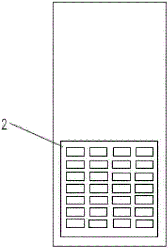
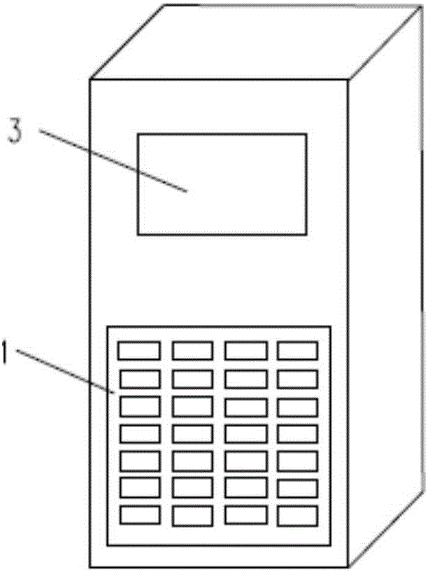
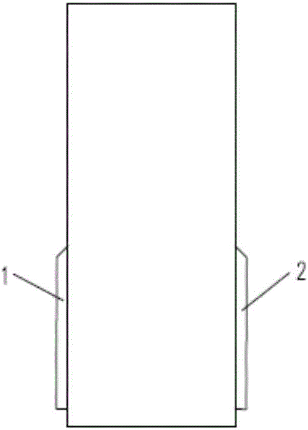
[0027] like Figures 1 to 3 As shown, the front of the electric vehicle DC charging pile body of the present invention includes an air inlet 1,...


PUM


Abstract

The invention provides an electric automobile DC charging pile heat dissipation apparatus and method. The apparatus comprises a grid matrix air inlet and an air outlet which are arranged on a pile body, and a temperature monitoring unit, a master unit, an air inlet adjustment unit and an air outlet adjustment unit which are arranged in the pile body and are connected with one another, wherein the temperature monitoring unit is used for monitoring a temperature inside the pile body and sending a temperature over-limit alarm signals to the master control unit; the master control unit is used for emitting air inlet and outlet adjustment commands according to the received temperature over-limit alarm signals; and the air inlet adjustment unit and the air outlet adjustment unit are used for adjusting the areas of the air inlet and the air outlet so as to release the temperature over-limit alarm signals. The area of the air inlet and the area of the air outlet can be adjusted, the problem of incapability of heat dissipation due to quite high temperature inside the pile body under the condition of a high environment temperature and in the operation process of the charging pile can be solved, and the conflict of difficult cabinet body protection due to too large air inlet and air outlet is also well solved.

Description

technical field [0001] The invention relates to the technical field of DC charging piles for electric vehicles, in particular to a cooling device and method for DC charging piles for electric vehicles. Background technique [0002] The DC charging pile will generate a lot of heat during the working process. If the heat is not discharged in time, the output power of the charging pile will be reduced. At present, the DC charging piles on the market all use fans to dissipate heat. Since the air inlet and outlet areas of the pile body are fixed, even if the fan rotates at the highest speed, the heat dissipation is still poor. [0003] Design defects of the current heat dissipation system: the existing heat dissipation system is designed for the size of the air inlet and outlet when the maximum power output of the charging pile. Such a design ignores a very important factor: the local atmospheric temperature. The charging pile outputs the same power at different ambient tempera...

Claims


Application Information

Patent Timeline
Patent Type & Authority Applications(China)
IPC IPC(8): H05K7/20
CPCH05K7/20909H05K7/20945
Inventor 张磊许善玉
Owner 特变电工南京智能电气有限公司
Learn More