

Optical unit for projection display apparatus and projection display apparatus
a projection display and optical unit technology, applied in the direction of printers, instruments, camera focusing arrangement, etc., can solve the problems of reduced light utilization efficiency, projection display apparatus suffers, projection image brightness is lowered or shaded, etc., to achieve easy adjustment of the area and improve light utilization efficiency
- Summary
- Abstract
- Description
- Claims
- Application Information
AI Technical Summary
Benefits of technology
Problems solved by technology
Method used
Image

Examples
Embodiment Construction
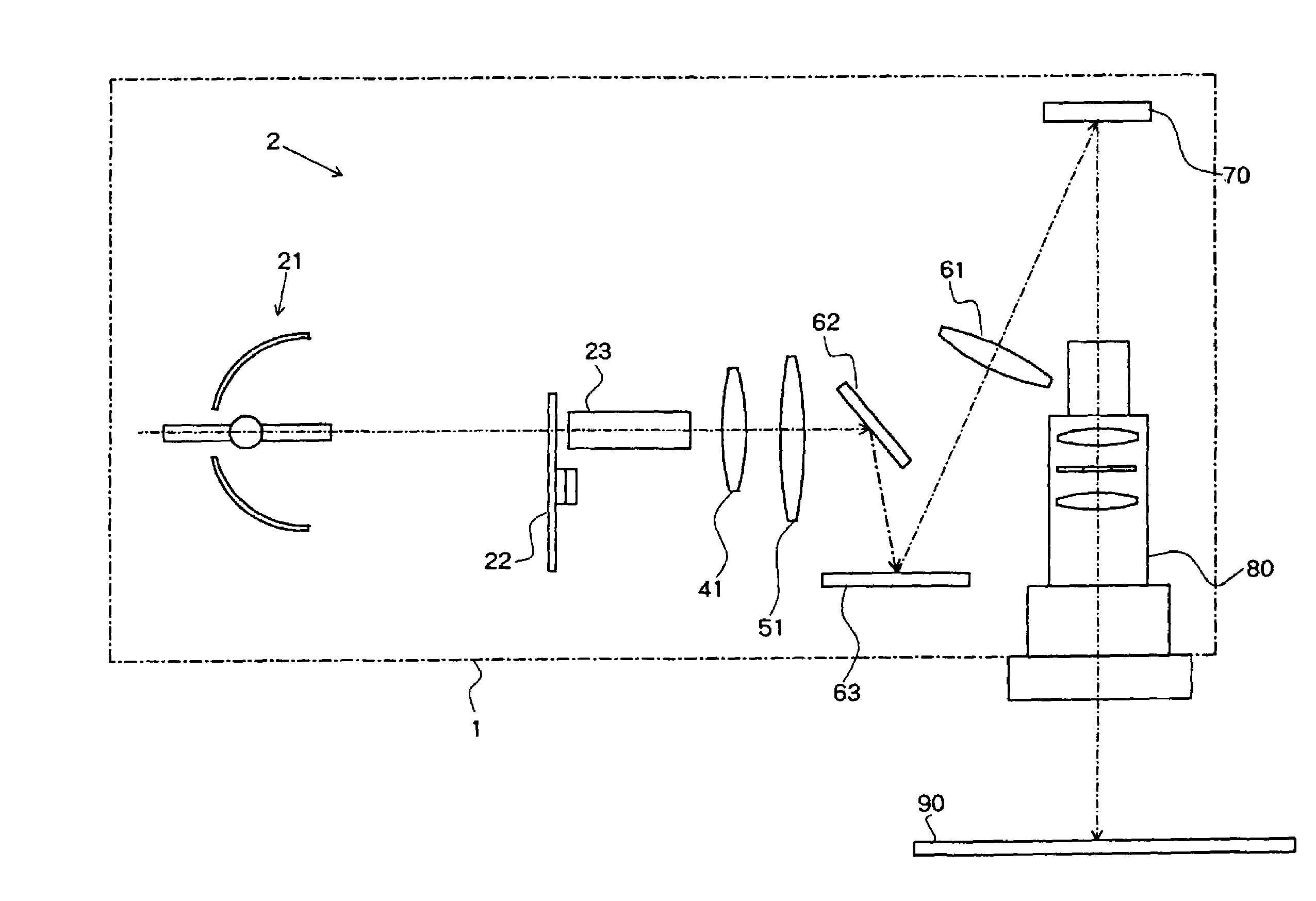
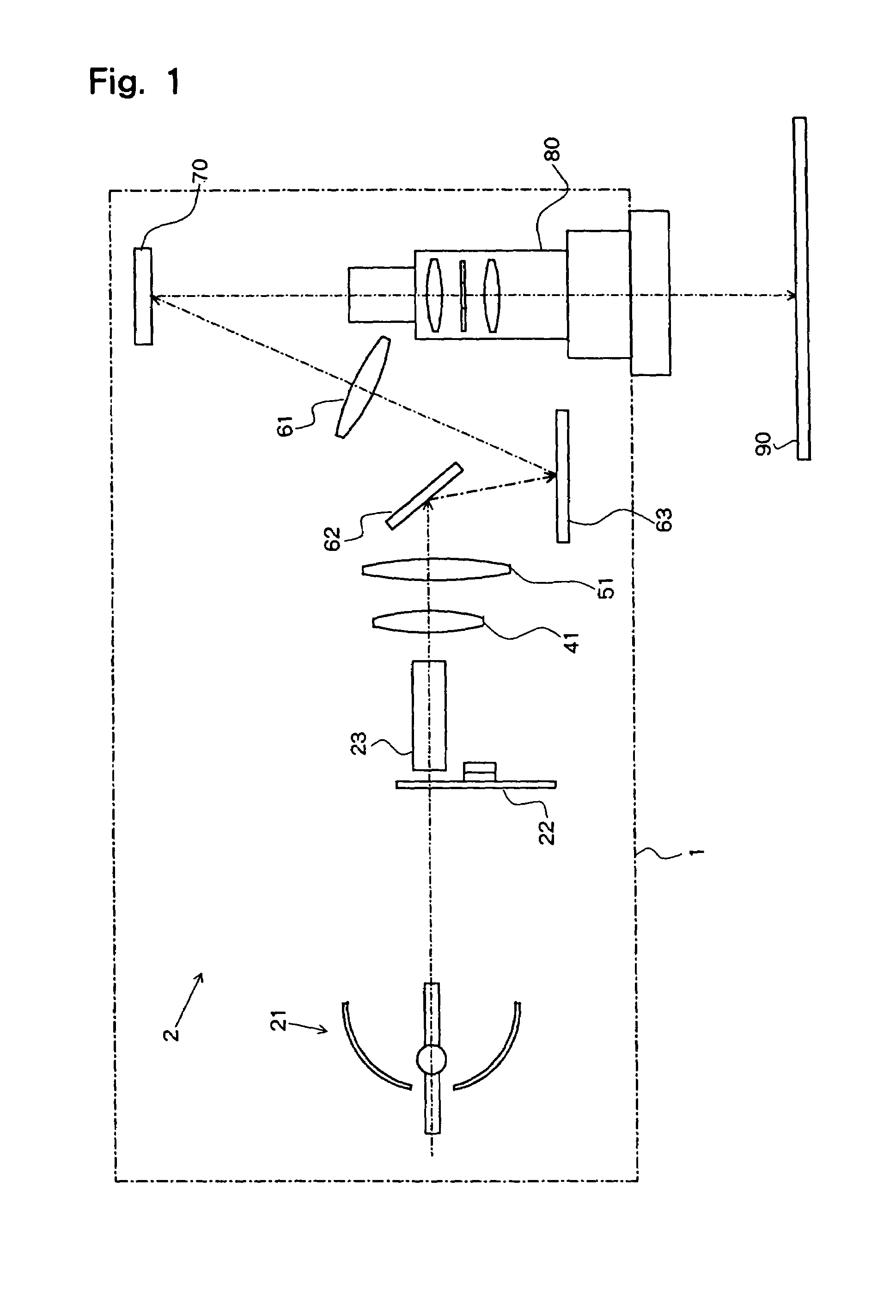
[0037]A projection display apparatus incorporating an optical unit according to an embodiment of the present invention will be described below with reference to the drawings. As shown in FIG. 1, optical unit 2 incorporated in projection display apparatus 1 comprises an illuminating optical system, DMD 70, and projection lens 80. The illuminating optical system illuminates DMD 70. DMD 70 is a reflective optical modulator serving as an image forming device. Projection lens 80 projects a light beam from DMD 70 onto screen 90.
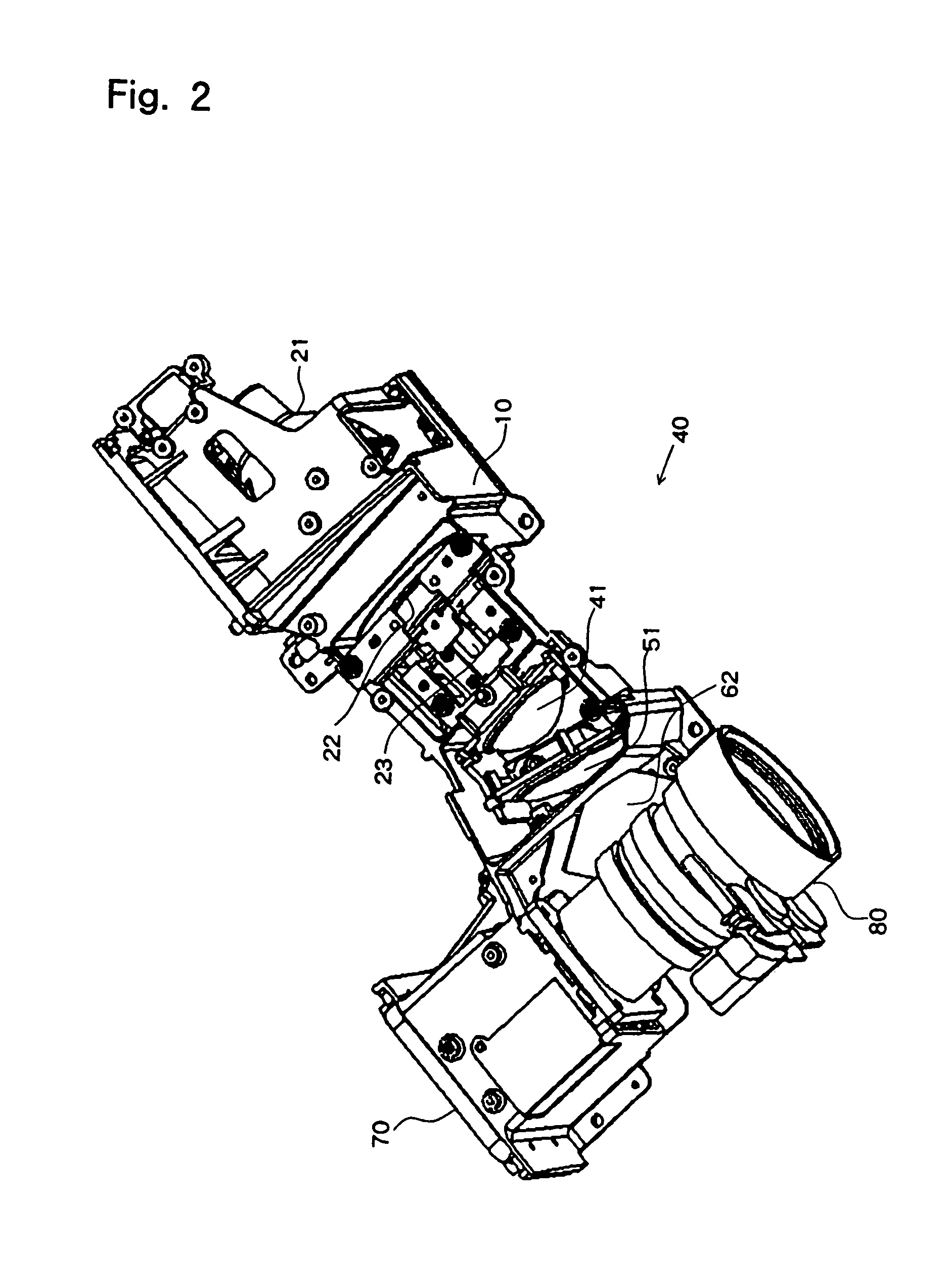
[0038]The illuminating optical system comprises light source unit 21, color wheel 22, light tunnel 23, and an afocal optical system.
[0039]Light source unit 21 comprises a light source having a light emitting body and a converging mirror for converging a light beam from the light source into a hypothetical secondary light source. Color wheel 22 has a plurality of color segments which can selectively be positioned at the point where the light beam from light source u...
PUM
 Abstract
Description
Claims
Application Information