

A Microstrip-Coaxial Vertical Transition Structure
A vertical transition, microstrip line technology, applied in antennas, antenna components, waveguide-type devices, etc., can solve the problems of impedance mismatch of transmission lines, narrowing of operating frequency bands, increase of insertion loss, etc., to avoid the deterioration of voltage standing wave ratio Effect
Inactive Publication Date: 2014-05-14
LEIHUA ELECTRONICS TECH RES INST AVIATION IND OF CHINA
View PDF0 Cites 8 Cited by
- Summary
- Abstract
- Description
- Claims
- Application Information
AI Technical Summary
Problems solved by technology
The disadvantage of the above structure is: the impedance of the connection position of the transition structure is capacitive, which causes the impedance mismatch of the two transmission lines, which makes the voltage standing wave ratio of the connection position of the transition structure deteriorate sharply, the insertion loss also increases sharply, and the working frequency band narrows
Method used
View moreImage
Smart ImageViewing Examples

Examples
example 1
example 2
Login to View More PUM
 Abstract
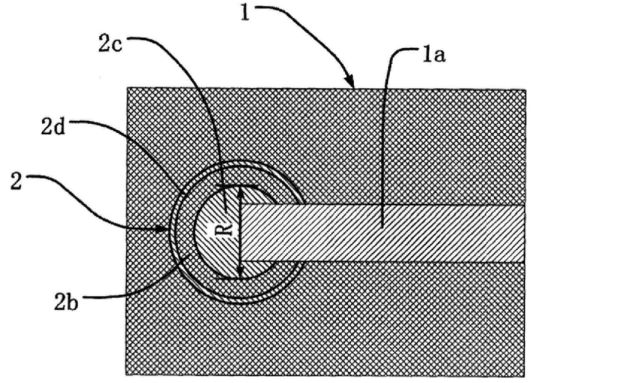
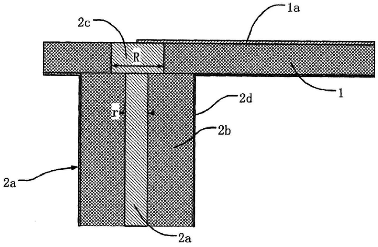
The invention belongs to microwave antenna technology and relates to the improvement of the microstrip line-coaxial vertical transition structure. Comprising a microstrip line [1] and a coaxial line [2] vertically connected to the microstrip line, it is characterized in that there is a transition conductor [2c] in the above-mentioned transition hole, and the upper end surface of the transition conductor [2c] is connected to the microstrip [ The edge of the end of 1a] is welded to form an electrical connection, and the lower end surface of the transition conductor [2c] is welded to the end of the inner conductor [2a] of the coaxial line [2] to form an electrical connection. The present invention makes the impedance of the connection position of the transition structure a resistive impedance, makes the impedances of the two transmission lines completely match, and avoids the problems of deterioration of voltage standing wave ratio, increase of insertion loss, and narrowing of working frequency band due to impedance mismatch.
Description
A Microstrip-Coaxial Vertical Transition Structure technical field The invention belongs to microwave antenna technology and relates to the improvement of the microstrip line-coaxial vertical transition structure. Background technique The microstrip-coaxial vertical transition structure is mainly used to reduce the volume of microwave devices and increase space utilization. The existing microstrip-coaxial vertical feed structure is composed of a microstrip line and a coaxial line vertically connected to the microstrip line. The microstrip line is composed of a double-sided copper clad laminate. There is a transition hole through the microstrip line on the microstrip line, and there is a relief hole on the copper foil around the lower port of the transition hole. The relief hole is coaxial with the transition hole, and the diameter of the relief hole is larger than the coaxial line The diameter of the insulating layer, the upper end surface of the coaxial insulating layer ...
Claims
Login to View More Application Information
Patent Timeline
 Patent Type & AuthorityPatents(China)
IPC IPC(8): H01P5/08H01Q1/00H01Q13/08
Inventor沈荣孔德武
OwnerLEIHUA ELECTRONICS TECH RES INST AVIATION IND OF CHINA