A combine harvester and its compound cleaning system

A cleaning and suction fan technology, applied to harvesters, cutters, agricultural machinery and implements, etc., can solve the problems of affecting the cleaning quality, grain pollution, discharge, and can only be stored in the separation cylinder, so as to ensure cleaning Effect, strong processing ability, good cleaning effect

Active Publication Date: 2018-12-18
HENAN UNIV OF SCI & TECH
View PDF1 Cites 0 Cited by
  • Summary
  • Abstract
  • Description
  • Claims
  • Application Information

AI Technical Summary

Problems solved by technology

[0004] In actual application, the cyclone separator has a lack of ability to deal with broken stalks. First of all, it has no ability to separate broken stalks whose specific gravity is greater than that of grains. The discharge of the grain mouth affects the cleaning effect; secondly, for some broken stalks whose specific gravity is equal to that of the grain, because their suspension speed is similar to that of the grain, they can neither be sucked out by the suction fan nor can they be taken out of the grain outlet together with the grain. Discharge can only be stored in the separation cylinder. When the amount of accumulation is large, it will affect the cleaning effect of the cyclone separation cylinder, and the bottom of the cyclone separation cylinder on the combine harvester is equipped with a grain tank to store the separated grains. When the cyclone separation cylinder is powered off and stops working, the hoarded broken stalks will fall into the grain tank under the action of gravity, causing pollution to the cleaned grains again, thus affecting the quality of cleaning

Method used


Image

  • A combine harvester and its compound cleaning system
  • A combine harvester and its compound cleaning system
  • A combine harvester and its compound cleaning system

Examples


Embodiment Construction

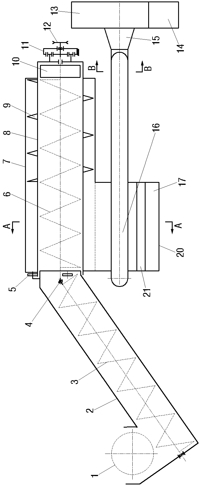
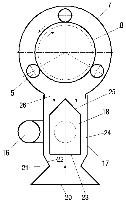
[0026] An example of a combine harvester such as Figure 1~Figure 4 As shown, it includes a frame (not shown in the figure), and a threshing device (not shown in the figure) and a compound cleaning system are arranged on the frame, and the compound cleaning system includes the third pusher 1, the second pusher 3 and the separation drum 8, the mixture of grains, glumes, and broken stalks threshed by the threshing device is transported to the bottom of the second auger 3 under the action of the third auger 1. The second auger 3 is arranged obliquely, and a material conveying pipeline 2 is arranged outside it. Under the rotation of the second auger 3 , the material to be cleaned is lifted to the material inlet of the separation drum 8 . The separation drum 8 is set horizontally, and its other end is provided with a grass outlet 10. The separation drum 8 is provided with a first pusher 6, and the rotation shafts of the first pusher 6 and the second pusher 3 pass through a coupling...


PUM


Abstract

The invention provides a combine harvester and a composite sorting system thereof. The composite sorting system comprises a separation rolling tube, wherein one end of the separation rolling tube is provided with a material inlet, and the other end of the separation rolling tube is provided with a grass discharging opening; a first push conveying device used for pushing materials from the material inlet end of the separation rolling tube to the grass discharging opening end is arranged in the separation rolling tube; separation holes only used for leaking out seeds and tiny sundries in the materials are formed in the separation rolling tube; a sorting box used for receiving seeds and tiny sundries is arranged under the separation rolling tube; an inner core is arranged in the sorting box; a passage through which the seeds and tiny sundries fall down is formed between the side surface of the inner core and the box wall of the sorting box; the lower end of the inner core is provided with a sundries inlet communicated with the air suction opening of an air suction machine so that after passing through the passage, the seeds and the tiny sundries can be discharged out of the sorting box through the sundries inlet and the air suction machine. Through the separation holes, the goal that broken stems and stalks can be discharged from the grass discharging opening and the tiny sundries can be sucked away by the sundry inlet after one-step sorting can be achieved; the secondary sorting is realized; the structure of the sorting system is simple; the sorting effect is better.

Description

technical field [0001] The invention relates to a combine harvester and a compound cleaning system thereof. Background technique [0002] The cleaning system is an important part of the grain combine harvester, and its performance directly affects the operation effect of the whole machine. At present, most grain combine harvesters widely adopt the cleaning method of fan and vibrating screen. Its structure is complex and bulky. Therefore, due to the limitation of power and space position, it is not suitable to configure " Fan-vibrating screen" type cleaning system. At present, for small grain combine harvesters with small feeding volume, simple air separation systems without sieves or cyclone separation cleaning systems are widely used. Although the simple air separation systems without sieves have simple structures, their cleaning quality is low. [0003] The authorized announcement number is CN203457560U, and the Chinese utility model patent whose authorized announcement ...

Claims


Application Information

Patent Timeline
Patent Type & Authority Patents(China)
IPC IPC(8): A01F12/44A01D41/00
CPCA01D41/00A01F12/442
Inventor 师清翔耿令新王升升许泽宇骆恒光杨兴超刘春亚
Owner HENAN UNIV OF SCI & TECH
Why Eureka
Try Eureka