A rolling bending machine for s spring

A technology of a roll bender and a machine base, applied in the mechanical field, can solve the problems of inability to realize the automatic feeding and automatic unloading of the S spring, the inability to ensure the uniformity of the bending of the S spring, and the inability to adjust the bending degree of the S spring, etc. To achieve the effect of preventing burning, reducing the occupied volume, and eliminating the need for manual cutting

Active Publication Date: 2018-01-30
浙江心梦享家居有限公司
View PDF1 Cites 0 Cited by
  • Summary
  • Abstract
  • Description
  • Claims
  • Application Information

AI Technical Summary

Problems solved by technology

[0004] However, there are many deficiencies in this multi-functional spring coil machine, such as: 1, the automatic feeding and automatic unloading of the S spring cannot be realized; 2, the bending degree of the S spring cannot be adjusted; 3, it cannot be guaranteed that each The bending uniformity of each S spring; 4. The production efficiency is relatively low

Method used


Image

  • A rolling bending machine for s spring
  • A rolling bending machine for s spring
  • A rolling bending machine for s spring

Examples


Embodiment Construction

[0033] The following are specific embodiments of the present invention and in conjunction with the accompanying drawings, the technical solutions of the present invention are further described, but the present invention is not limited to these embodiments.

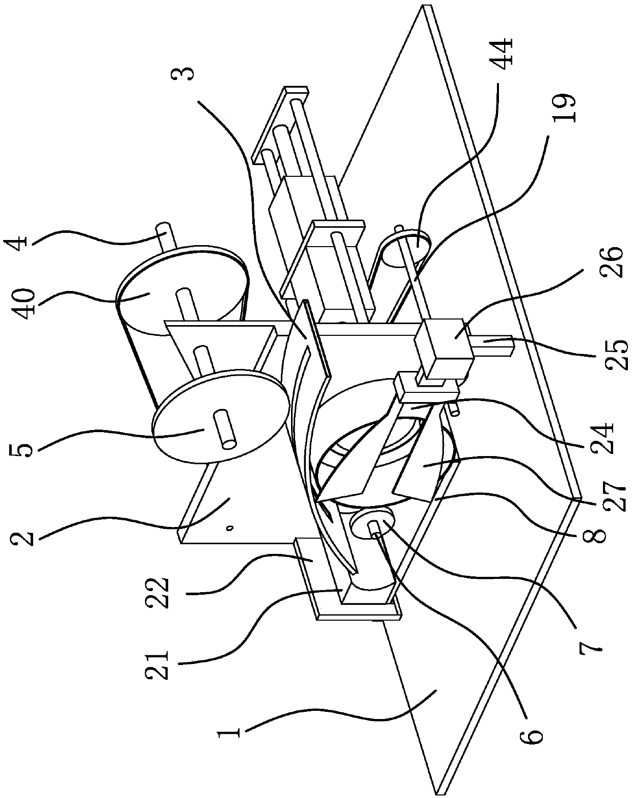
[0034] Such as figure 1 As shown, a rolling bending machine of an S spring includes a machine base 1 and a riser 2 vertically welded and fixed on the machine base 1. One side of the riser 2 is welded and fixed with a conveying rail 3 with a conveying channel inside, and the conveying The rail 3 is arc-shaped, and there is a long hole on the conveying rail 3. The vertical plate 2 is fixed with a rotating shaft 4 by means of circumferential rotation and axial fixing. The gear 5 and the traveling gear 5 are located above the conveying rail 3 and the teeth of the traveling gear 5 extend into the elongated holes. The vertical plate 2 is also fixed with a rotating shaft 2 6 by means of circumferential rotation and axial fixing. ...


PUM


Abstract

The invention provides an S spring roll bending machine, which belongs to the technical field of machinery, and solves the problem of low roll bending efficiency of S springs in the prior art. The S spring roll bending machine comprises a machine seat and a vertical plate vertically fixed on the machine seat, wherein a conveying rail with a conveying passage at the inside is fixedly arranged at one side of the vertical plate; the conveying rail is in an arc shape; a long slotted hole is formed in the conveying rail; a first rotating shaft is fixed on the vertical plate in a peripheral rotation axial fixing mode; an advancing gear capable of driving an S spring to forwards move is fixed on the first rotating shaft; the advancing gear is positioned above the conveying rail; in addition, teeth of the advancing gear extend into the long slotted hole; a second rotating shaft is also fixed on the vertical plate in a peripheral rotation axial fixing mode; a bending gear enabling the S ring to bend is fixed on the second rotating shaft; the bending gear is positioned at the discharging end of the conveying rail; a regulating structure capable of regulating the bending degree of the S spring is arranged at one side of the bending gear; a guide rail is arranged at the other side of the bending gear. The S spring roll bending machine has the advantage that the S spring roll bending efficiency is improved.

Description

technical field [0001] The invention belongs to the technical field of machinery, and relates to a bending machine, in particular to a bending machine for S springs. Background technique [0002] S spring is a very common spring. A large number of S springs are used in sofas and cushions. After some S springs are processed, due to the needs of customers, the bent S springs must be re-bent at point A. Bending to meet customer requirements. The previous operation method is to clamp the S spring on the mold base and rely on manpower to bend. However, this method not only cannot guarantee the accuracy of the bending, but also takes time for the operator. Laborious, seriously affecting the quality of processing efficiency and products. [0003] After searching, for example, Chinese patent literature discloses a multifunctional spring coil circular machine [patent number: ZL201020106290.5; authorized announcement number: 201632567U]. This multifunctional spring coil machine incl...

Claims


Application Information

Patent Timeline
Patent Type & Authority Patents(China)
IPC IPC(8): B21F1/00B21F23/00
CPCB21F1/004B21F23/00
Inventor 顾伟杰金祥华孙毅朱宏伟
Owner 浙江心梦享家居有限公司
Why Eureka
Try Eureka