Mating equipment with vision for motor detection

A technology for visual devices and equipment, applied in electromechanical devices, metal processing equipment, manufacturing motor generators, etc., can solve problems such as low efficiency, achieve high production efficiency, stable installation quality, and high degree of automation.

Active Publication Date: 2018-10-09
嘉兴岱森科技有限公司
View PDF8 Cites 0 Cited by
  • Summary
  • Abstract
  • Description
  • Claims
  • Application Information

AI Technical Summary

Problems solved by technology

The circlip used on the motor shaft is an E-shaped circlip (of course, it is also possible to use a U-shaped circlip), and the circlip is provided with a card entrance that is opened by extrusion; in the production process of the motor, it is currently manual Assembling the circlip onto the motor shaft is less efficient

Method used


Image

  • Mating equipment with vision for motor detection
  • Mating equipment with vision for motor detection
  • Mating equipment with vision for motor detection

Examples


Embodiment

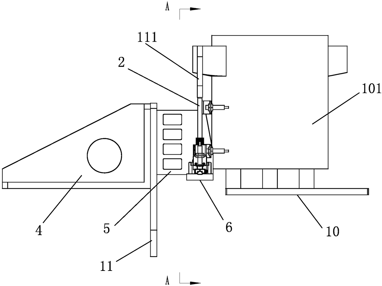
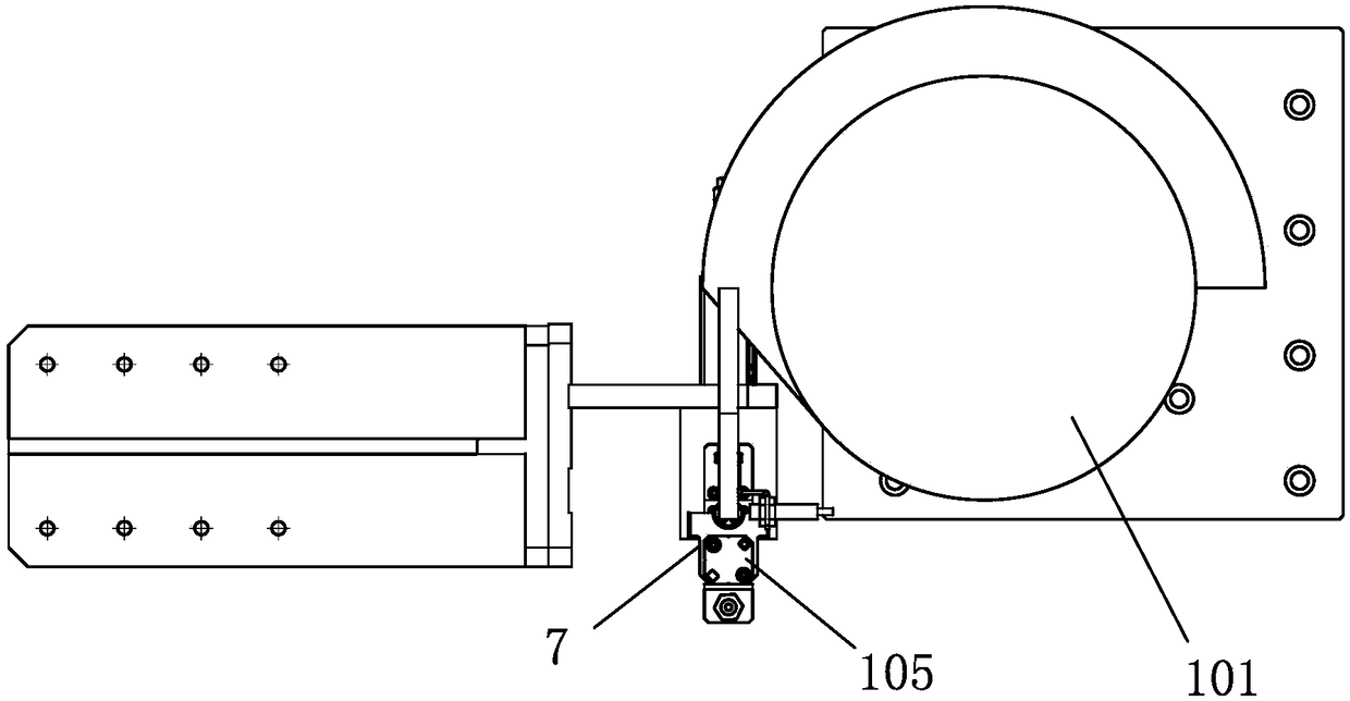
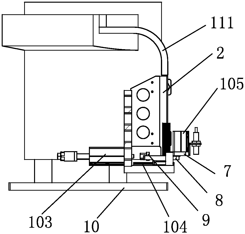
[0021] Embodiment: The present invention has the mating equipment of motor detection visual device, as attached figure 1 , attached figure 2 , attached image 3 , attached Figure 4 , attached Figure 10 As shown, it includes a frame 1001, a clip spring device 1002, a motor fine positioning device 1003, a clip spring material distribution device 1004, a visual fixing device 1005, a workpiece tray 1007, a fixed lift positioning stop 1008, and a workpiece from the frame 1001 to The workpiece tray 1009 that passes through from the side to the other side; the circlip distributing device 1004 includes an installation connecting plate 5, on which the circlip guide 2 is vertically placed on the installation connecting plate 5, and the combined bottom plate 6 is placed flat on the bottom, and the combined bottom plate 6 is set The material distribution cylinder 103, the linear slide rail 104 and the connecting support 7 are arranged horizontally, and the diverter plate 8 is arrang...


PUM


Abstract

The invention relates to insertion equipment with a visual motor detection device. The insertion equipment comprises a rack, a clamp spring insertion device, a precise motor positioning device, a clamp spring distribution device, a visual fixing device, a first workpiece tray, a fixed lifting positioning stop and a second workpiece tray for allowing a workpiece to penetrate from one side of the rack to the other side of the rack; the clamp spring distribution device comprises an installation connecting plate, a clamp spring guide part is vertically arranged on the installation connecting plate, a combination base plate is horizontally arranged at the bottom of the installation connecting plate and provided with a transversely-arranged distribution air cylinder, a linear sliding rail and a connecting support, and a splitter plate is arranged on a sliding block of the linear sliding rail, located under the clamp spring guide part and connected with the distribution air cylinder; a clamping air cylinder is arranged on the connecting support and located above the sliding direction of the linear sliding rail. By means of the splitter plate and the distribution air cylinder, motor clamp springs at the bottom of the clamp spring guide part can be conveniently and quickly moved out, and the clamping air cylinder grasps the motor clamp springs from splitter heads to sort the motor clamp springs; the whole process is high in automation degree, and the production efficiency is significantly improved.

Description

technical field [0001] The invention relates to an assembly device, in particular to a plug-in device with a visual device for motor detection. Background technique [0002] The motor circlip is a part on the motor shaft. In mass production, it is necessary to quickly and accurately install the motor circlip on the motor shaft. The two motor shafts often rotate during the assembly process, and it is difficult to accurately and accurately locate them in the circumferential direction; patented in China A motor is disclosed in the patent document with the publication number CN104539078 and the name "Permanent Magnet Brushless Motor with Dust Structure on the Rotor". In order to prevent axial displacement of the parts connected to the motor shaft, a circlip is installed on the motor shaft, and a positioning plane is provided on the peripheral surface of the end of the motor shaft provided with the circlip groove. The circlip used on the motor shaft is an E-shaped circlip (of co...

Claims


Application Information

Patent Timeline
Patent Type & Authority Patents(China)
IPC IPC(8): B23P19/08B23P19/00H02K15/00
CPCB23P19/002B23P19/084H02K15/00
Inventor 蔡永潮陈敬生何永全方勇
Owner 嘉兴岱森科技有限公司
Why Eureka
Try Eureka