Anti-collision bar for automobile body

A technology of automobile body and anti-collision strips, which is applied to vehicle parts, transportation and packaging, etc., can solve the problems of poor anti-collision effect and complex processing technology of anti-collision strips, and achieve lower product quality, good impact resistance, and good The effect of absorbing impact energy

Inactive Publication Date: 2017-01-25
夏志清
View PDF0 Cites 1 Cited by
  • Summary
  • Abstract
  • Description
  • Claims
  • Application Information

AI Technical Summary

Problems solved by technology

The existing anti-collision strip has complex processing technology and poor anti-collision effect

Method used


Image

  • Anti-collision bar for automobile body
  • Anti-collision bar for automobile body

Examples


Embodiment Construction

[0022] In order to have a clearer understanding of the technical features, purposes and effects of the present invention, the specific implementation manners of the present invention are now described in detail.

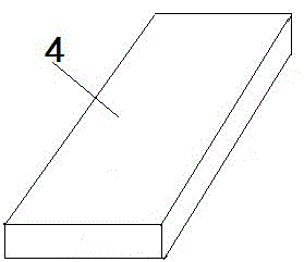
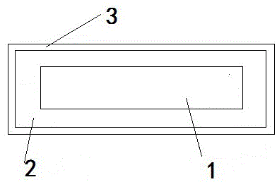
[0023] Such as figure 1 and figure 2 Shown is an anti-collision strip 4 for an automobile body, the core of which is a particle-reinforced foamed aluminum-based composite material 1, the core is surrounded by an elastic material layer 2, and the outer layer of the elastic material is a rectangular steel pipe 3.

[0024] An anti-collision strip for an automobile body, the core of which is a particle-reinforced foamed aluminum-based composite material, the core is wrapped with an elastic material layer, and the outer layer of the elastic material is a rectangular steel pipe, which is characterized in that:

[0025] The particle-reinforced foamed aluminum-based composite material is prepared by the following preparation method:

[0026] Prepare an aluminum alloy ingo...


PUM

PropertyMeasurementUnit
particle diameteraaaaaaaaaa

Abstract

The invention discloses an anti-collision bar for an automobile body. A core part of the anti-collision bar is made of a particle enhanced foam aluminum-based composite material; an elastic material layer surrounds the core part; a rectangular steel pipe is arranged outside the elastic material layer. An iron-based alloy material fully meets the requirement on external intensity of a product; aluminum-based alloy better ensures that the product is better in impact resistance effect; meanwhile, the mass of the product is reduced.

Description

technical field [0001] The invention relates to an anti-collision strip for an automobile body, belonging to the technical field of auto parts. Background technique [0002] When we drive daily, we will inevitably encounter small scratches and bumps, which will seriously affect the body of our car. If we don’t go out for a long time, it is easy to rust. In order to protect our car models, many car owners Began to install car anti-collision strips for cars, car anti-collision strips are also called protective strips, anti-scratch strips, etc. Prevent the side of the car body from being scratched or bruised by foreign objects, and play a protective role. The existing anti-collision strip has complicated processing technology and poor anti-collision effect. Contents of the invention [0003] An anti-collision strip for an automobile body, the core of which is a particle-reinforced foamed aluminum-based composite material, the core is wrapped with an elastic material layer, ...

Claims


Application Information

Patent Timeline
Patent Type & Authority Applications(China)
IPC IPC(8): C22C21/08C22C1/08C22C38/08C22C38/18C22C38/10C22C38/12C22C38/02C22C38/06C22C38/16C22C38/14C22C33/06C21D1/18C21D8/10C08L63/00C08K3/08C08K3/26B60R13/04
CPCC21D1/18C21D8/105C22C1/026C22C1/03C22C1/08C22C21/08C22C32/0005C22C32/0036C22C32/0063C22C33/06C22C38/002C22C38/005C22C38/02C22C38/06C22C38/105C22C38/12C22C38/14C22C38/16C22C38/18C08K3/08C08K3/26C08L63/00B60R13/04C08K2003/265C08K2003/0856C22C1/086C08L71/00
Inventor 夏志清
Owner 夏志清
Why Eureka
Try Eureka