

Pendulum type wave energy power generation device
A power generation device and wave energy technology, which is applied in ocean energy power generation, hydropower generation, engine components, etc., can solve the problems of inability to generate large-scale power generation
Active Publication Date: 2017-01-25
山东九木氢能科技股份有限公司
View PDF6 Cites 6 Cited by
- Summary
- Abstract
- Description
- Claims
- Application Information
AI Technical Summary
Problems solved by technology
[0002] Ocean wave power generation devices currently in use or applied for are only suitable for small-scale power generation equipment and cannot be used for large-scale power generation
Method used
View moreImage
Smart ImageViewing Examples

Examples
Embodiment Construction
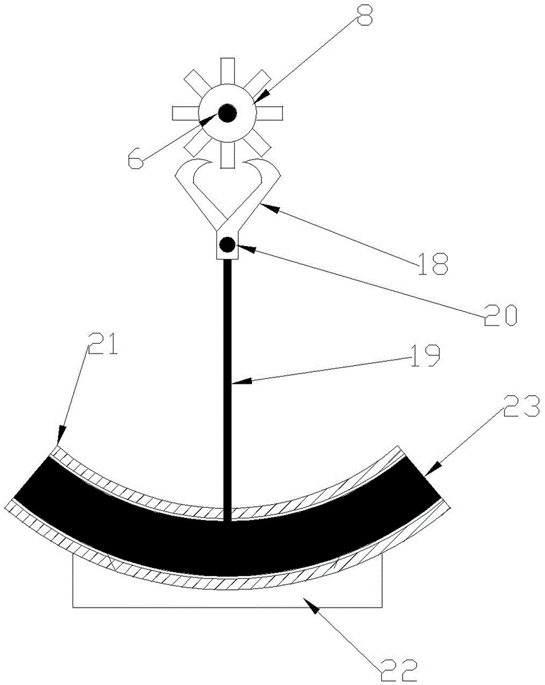
[0011] The content of the invention has described the specific implementation manner of the present invention in detail, does not repeat here, need explain: see Figure 5 , if the winding groups of the stator 21 are divided into five groups of A, B, C, D, and E, the middlemost group E is a single group of positive and negative outgoing wires, and group B and D are connected in parallel to positive and negative outgoing wires. The positive and negative poles of the group and the E group are connected in parallel.
Login to View More PUM
 Abstract
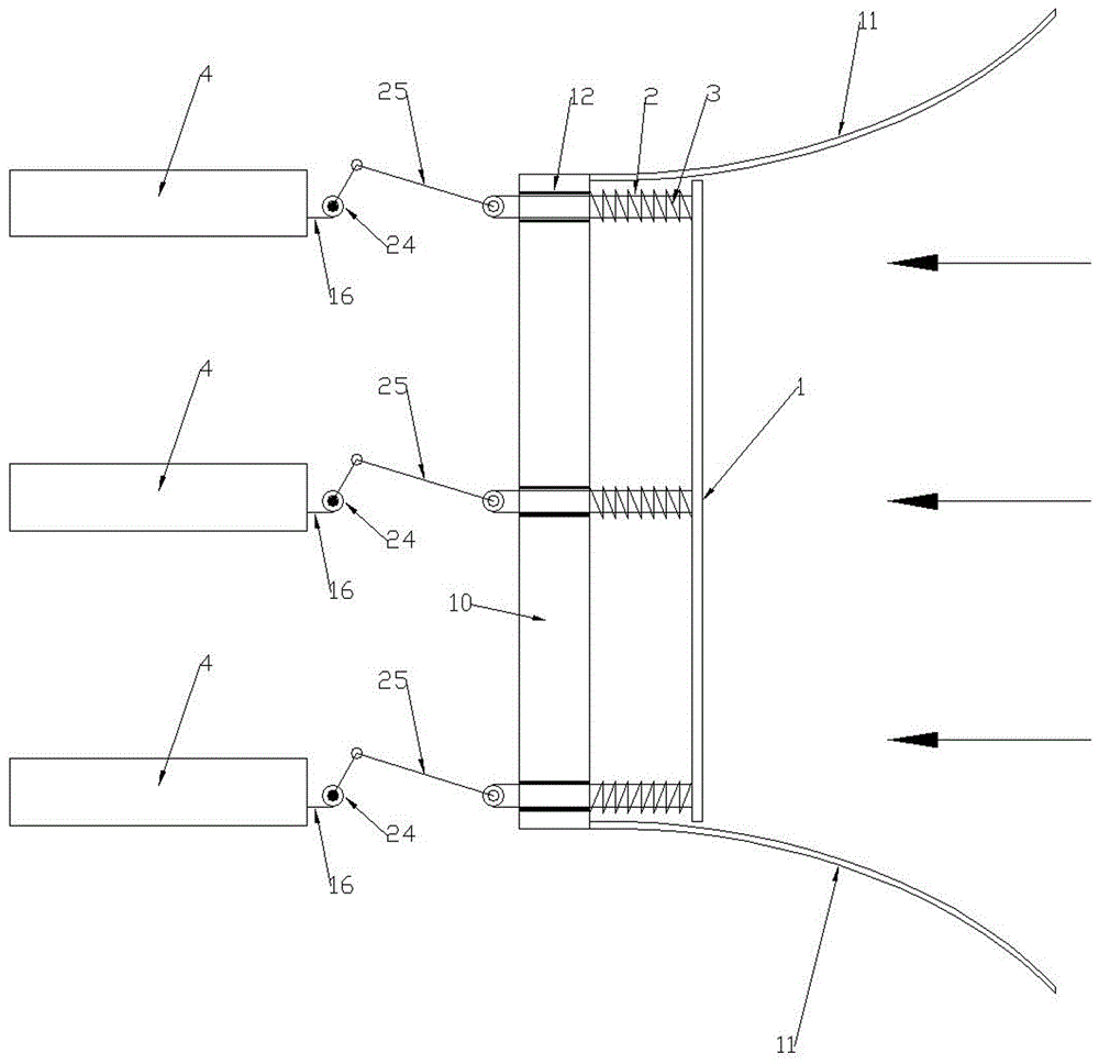
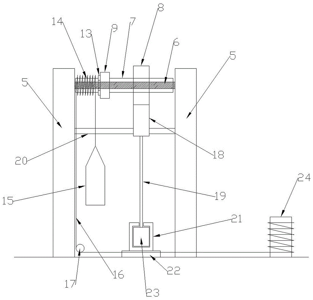
The invention relates to a pendulum type wave energy power generation device, which is mainly used for ocean wave energy power generation. The pendulum type wave energy power generation device mainly consists of a push plate 1, slide rods 2, springs 3, pendulum power generation devices 4, a blocking wall 10, floating type flow guide walls 11, round tube slide sleeves 12, wheels B24 and connecting rod groups 25, wherein the floating type flow guide walls 11 gather ocean waves for pushing the push plate 1 to do to-and-fro movement; the to-and-fro movement of the push plate 1 pulls heavy punches 15 of the pendulum power generation devices 4 to ascend through the connecting rod groups 25; potential energy is provided for the pendulum power generation devices 4; the pendulum power generation devices 4 enable rotors 23 to swing to and fro in grooves of stators 21 through escapement wheels 8 and escapement pawls 18; permanent magnetic fields of the rotors 23 sweep coils in the stators 21 to and fro, so that the stable power quantity is given. The pendulum type wave energy power generation device has the advantages that the generated current is stable; complicated control equipment is not needed; the pendulum type wave energy power generation device can be directly connected to grid with state grids.
Description
technical field [0001] The invention is mainly used for ocean wave power generation. Background technique [0002] The currently used or applied ocean wave power generation devices are only suitable for small-scale power generation equipment and cannot be used for large-scale power generation. Contents of the invention [0003] The present invention can generate electricity on a large scale and the electricity generated is stable, and can be directly connected to the national grid; (10), floating diversion wall (11), cylindrical sliding sleeve (12), wheel B (24), connecting rod group (25); the left end of spring (3) is fixed with retaining wall (10), and the spring The right end of (3) is fixed with the push plate (1); the sliding rod (2) penetrates the spring (3) and passes through the cylindrical sliding sleeve (12), and the right end of the sliding rod (2) is fixed with the push plate (1). The left end of the slide bar (2) is hinged with the right end of the long conn...
Claims
Login to View More Application Information
Patent Timeline
 Patent Type & AuthorityApplications(China)
IPC IPC(8): F03B13/18F03B11/00
CPCF03B11/00F03B13/18Y02E10/20Y02E10/30
Inventor彭宝安
Owner山东九木氢能科技股份有限公司