Airflow exchange device

A technology of airflow exchange and shoulders, which is applied in the direction of pipeline layout, household heating, space heating and ventilation details, etc. It can solve the problem of lack of axial positioning structure, poor joint stability, and isolation and blocking effect of airflow exchange device 9 Poor and other issues

Inactive Publication Date: 2017-01-25
SUNONWEALTH ELECTRIC MACHINE IND
View PDF8 Cites 2 Cited by
  • Summary
  • Abstract
  • Description
  • Claims
  • Application Information

AI Technical Summary

Problems solved by technology

[0004] However, the above-mentioned sleeve cover 94 or the above-mentioned indoor unit 95 is only fitted on the outer peripheral surface of the air-guiding pipe body 91, and in the axial direction of the above-mentioned air-guiding pipe body 91 (generally referring to the flow direction of the airflow guided by the above-mentioned fan 93), Since there is no axial positioning structure between the cover 94 or the indoor unit 95 and the air guide pipe body 91, the cover 94 or the indoor unit 95 may be placed on the air guide pipe body 91 due to external force. A...

Method used


Image

  • Airflow exchange device
  • Airflow exchange device
  • Airflow exchange device

Examples


Embodiment Construction

[0073] In order to make the above-mentioned and other objects, features and advantages of the present invention more obvious and easy to understand, preferred embodiments of the present invention are hereinafter described in detail with the accompanying drawings.

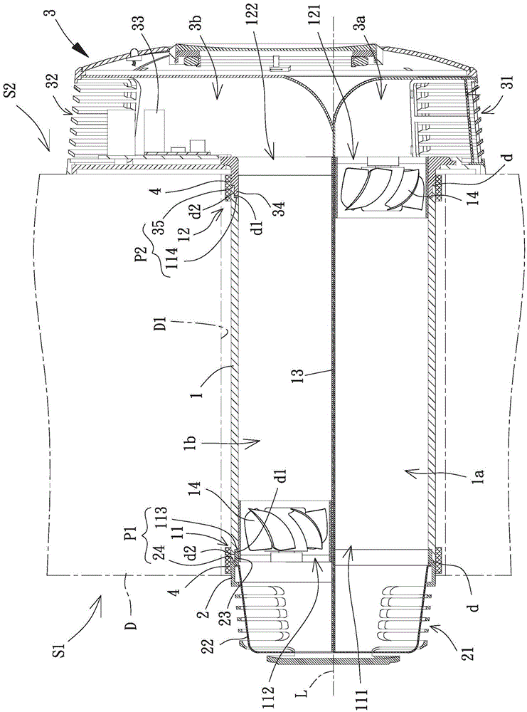
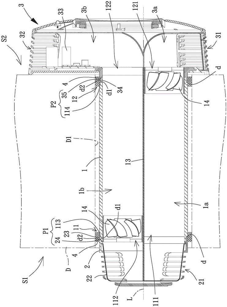
[0074] Please refer to figure 2 As shown, the airflow exchange device of the present invention is installed on a spacer D, one side of the spacer D is an outer space S1, and the opposite side of the spacer D is an inner space S2. The airflow exchange device includes an air duct body 1, the air duct body 1 is installed in a mounting hole D1 of the isolator D, and opposite ends of the air duct body 1 are at least combined with a cover 2 or An indoor unit 3. In this embodiment, opposite ends of the air duct body 1 are combined with the cover 2 and the indoor unit 3 at the same time.

[0075] The opposite ends of the air guide body 1 are respectively provided with an outer guide end 11 and an inner guide end 12 , and...


PUM


Abstract

The invention provides an airflow exchange device which solves the problem that a conventional airflow exchange device is poor in combination steadiness and isolation and blocking problem. This airflow exchange device contains a wind-guiding body, and the opposite ends of this wind-guiding body combines an upper shield or an indoor set at least. Wherein the binding site between this wind-guiding body and this upper shield is equipped with one and blocks piece and at least one axial positioning portion, perhaps, the binding site between this wind-guiding body and this indoor set is equipped with one and blocks piece and at least one axial positioning portion.

Description

technical field [0001] The present invention relates to an airflow exchange device, especially an airflow exchange device that can provide ventilation and ventilation function and can be firmly combined with a predetermined position of a partition. Background technique [0002] Please refer to figure 1 As shown, an existing airflow exchange device 9 is disclosed. The airflow exchange device 9 includes an air duct body 91 , a partition member 92 and two fans 93 . The partition member 92 is disposed inside the air duct body 91 to divide it into a first air guiding space 91a and a second air guiding space 91b, and the two fans 93 are respectively combined with the first air guiding space 91a and the second air guiding space 91b. The second guide space 91b. The airflow exchanging device 9 can be installed in a mounting hole D1 of a partition D (such as an outer wall, etc.) In the outer space S1 and an inner space S2. [0003] In addition, the two ends 911 and 912 of the air ...

Claims


Application Information

Patent Timeline
IPC IPC(8): F24F7/08F24F13/02F24F11/02F24F13/28
CPCF24F7/08F24F13/02F24F13/28F24F2221/17F24F11/89
Inventor 洪银树李明聪
Owner SUNONWEALTH ELECTRIC MACHINE IND
Why Eureka
Try Eureka