Radiating module

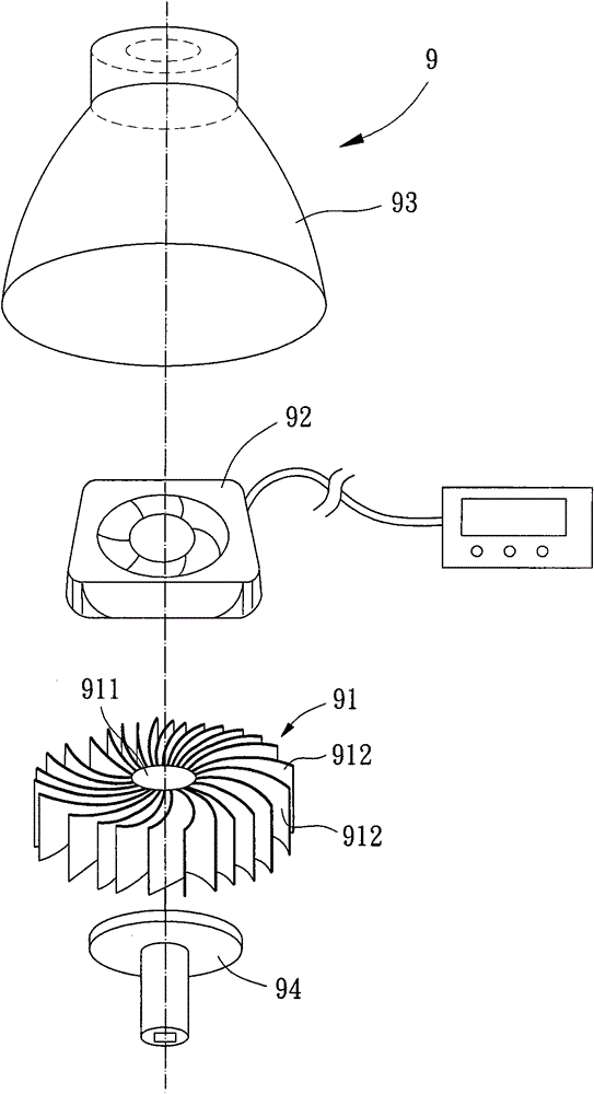
A technology of heat dissipation module and radiator, which is applied in the direction of instruments, electrical digital data processing, electrical components, etc., can solve the problems of reducing the air-displacement effect of the fan 92, easy to produce looseness, and the heat dissipation effect of the heat dissipation module 9 is reduced, and achieves a high level of improvement. The effect of making convenience

Active Publication Date: 2013-02-06
SUNON ELECTRONICS KUNSHAN
View PDF6 Cites 0 Cited by
  • Summary
  • Abstract
  • Description
  • Claims
  • Application Information

AI Technical Summary

Problems solved by technology

[0006] With the help of the structural design of the heat sink 91 of the existing heat dissipation module 9, in the axial direction of the fan 92, the opposite ends of the fins 912 in the axial direction are all open, so that the fan 92 introduces airflow axially through each of the fins. During the process between the fins 912, it can effectively avoid the airflow generated such as figure 2 The turbulence phenomenon of the heat dissipation module 8 shown; Yet, because the radiator 91 of this existing heat dissipation module 9 and this lamp holder 94 are not provided with such as figure 2 The heat spreader 83 and other components shown; therefore, the high heat generated by the operation of the lamp holder 94 cannot be evenly diffused and conducted to the radiator 91, resulting in a reduction in the heat dissipation effect of the existing heat dissipation module 9; moreover, the fan 92 and the radiator 91 do not have a design that can improve the stability of the combination, resulting in problems such as loosening of the fan 92 during operation.
[0007] What's more, even if there is a related business person who wants to directly place such a lamp between the radiator 91 and the lamp holder 94 figure 2 Shown components such as the heat spreader 83, but due to the special structural design of the radiator 91, the airflow guided by the fan 92 must axially pass between each of the fins 912; If the setting position of the heat spreader is inappropriate, or the relative positional relationship between the heat spreader and the fan 92 is not properly considered, the additional heat spreader may cause great hindrance to the axial circulation of the airflow, and reduce the air flow on the contrary. The wind-dispelling effect of fan 92, therefore, this existing cooling module 9 really needs to be improved

Method used


Image

  • Radiating module
  • Radiating module
  • Radiating module

Examples


Embodiment Construction

[0038] In order to make the above-mentioned and other objects, features and advantages of the present invention more comprehensible, the preferred embodiments of the present invention are specifically cited below, together with the accompanying drawings, as follows:

[0039] Please refer to Figure 4 and 5 As shown, the heat dissipation module of the preferred embodiment of the present invention includes a radiator 1 , a fan 2 and a heat spreader 3 . The fan 2 is combined with one end of the radiator 1 , and the heat spreader 3 is combined with the other end of the radiator 1 , so that the radiator 1 can be located between the fan 2 and the heat spreader 3 .

[0040] The heat sink 1 has a central body 11, the central body 11 is provided with a first end surface 111 and a second end surface 112 in the axial direction, and the outer peripheral surface of the central body 11 is provided with several fins 12, each of the fins 12 extends radially outward and is located between th...


PUM


Abstract

The invention discloses a radiating module, which comprises a radiator, a fan and a soaking piece, wherein the radiator is provided with a central body; a plurality of fins are arranged at the periphery of the central body; the fan is combined to one end of the radiator and is provided with a fan frame; the fan frame is provided with an axial airflow channel; a fan wheel is arranged inside the axial airflow channel and is provided with a hub; a plurality of blades are arranged at the periphery of the hub; the axial airflow channel has the maximum caliber in a radial direction of the fan wheel; the soaking piece is combined to the other end of the radiator; the maximum outer diameter of the hub in the radial direction is equal to or less than the maximum outer diameter of the central body in the radial direction; and the maximum caliber of the axial airflow channel of the fan is greater than the maximum outer diameter of the soaking piece in the radial direction. Therefore, a radiatingeffect is improved, airflow driven by the fan can smoothly circulate, and the fan and the radiator can be stably combined.

Description

technical field [0001] The invention relates to a heat dissipation module, in particular to a heat dissipation module with a heat equalizing element. Background technique [0002] For example, China Taiwan No. I279899 "Oscillating Heat Spreader with Flat Structure" patent case discloses an existing heat dissipation module with heat spreader, please refer to figure 1 As shown, the cooling module 8 generally has a radiator 81 , a fan device 82 and a heat spreader 83 . The radiator 81 has a base plate 811, a plurality of fins 812 are formed on one side surface of the base plate 811, and there are gaps between each of the fins 812; 811 is opposite; the heat spreader 83 is combined with the other side surface of the substrate 811 , and the heat spreader 83 can be combined with a central processing unit 84 . [0003] Please refer to figure 2 As shown in FIG. 1 , it discloses a schematic diagram of the actual heat dissipation of the existing heat dissipation module 8 . Wherein...

Claims


Application Information

Patent Timeline
Patent Type & Authority Patents(China)
IPC IPC(8): G06F1/20H01L23/367H01L23/467
Inventor 洪银树蔡期琮
Owner SUNON ELECTRONICS KUNSHAN
Why Eureka
Try Eureka